
BUILDING AN ARDUINO BOARD |
|
(Click on any image for a full-size view.) |
|
To successfully deploy Arduino projects, you need some basic infrastructure: An Arduino board, a power supply and I/O connectors. Below is one approach to building such an assembly. |
|
 |
 |
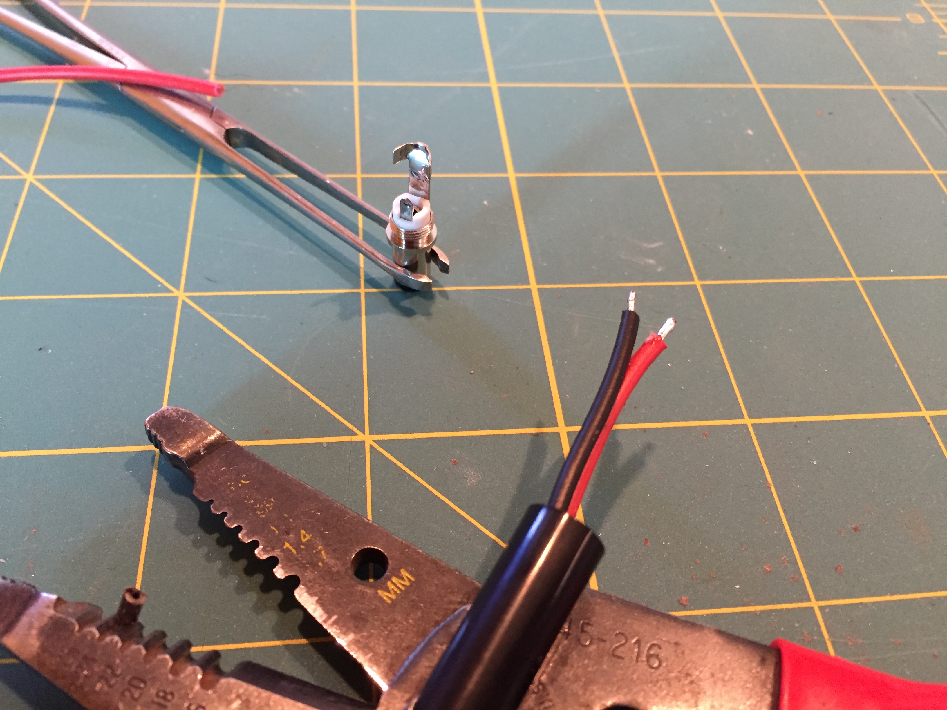
First you need a power connector. The power connector for an Arduino is 5mm OD and 2.5mm ID. Above shows preparing the connector. The leads and the connection points are tinned. Don't forget to put the back-shell on if the leads are not bare on the other end. |
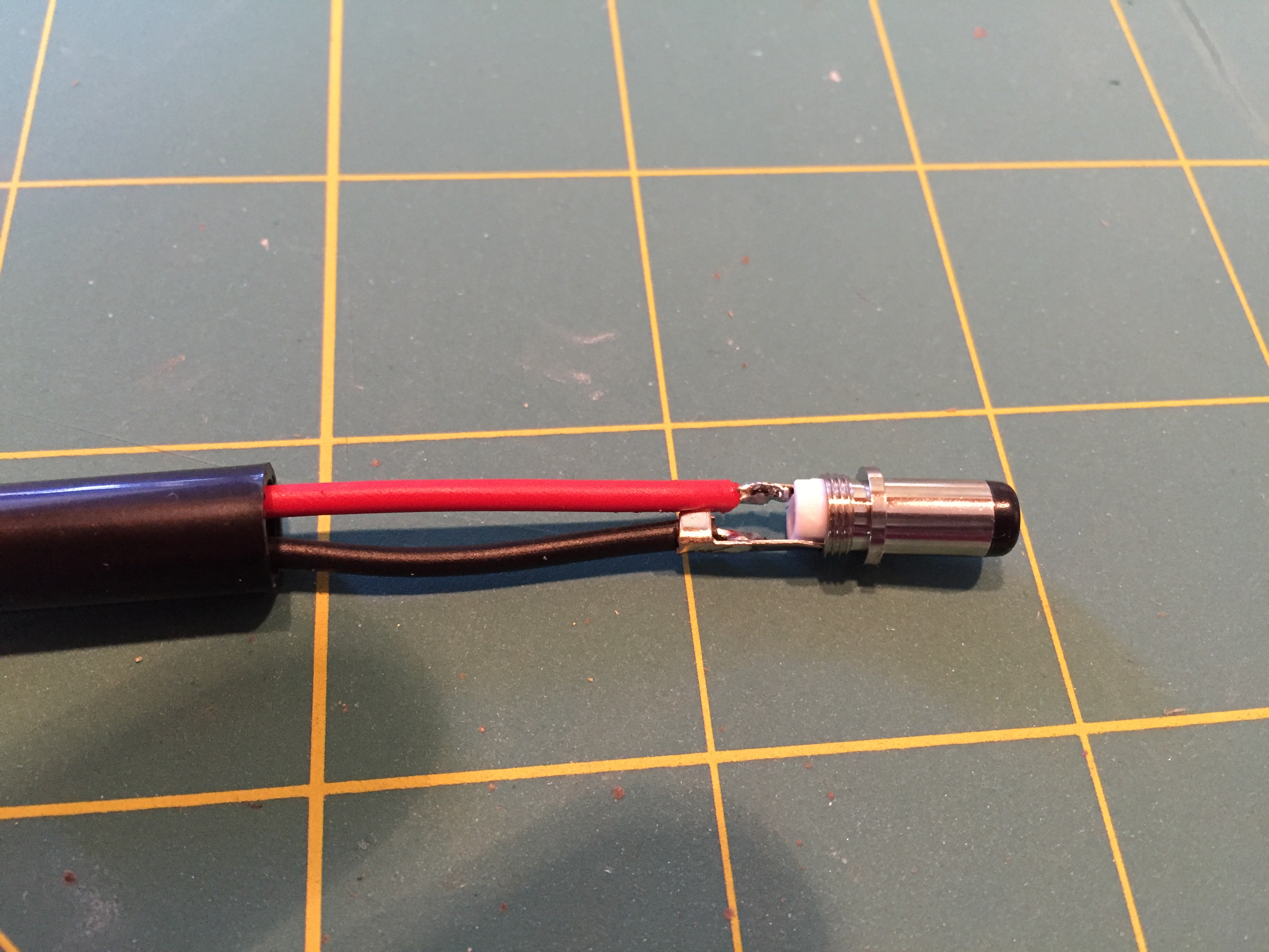
After the connector is soldered. |
 |
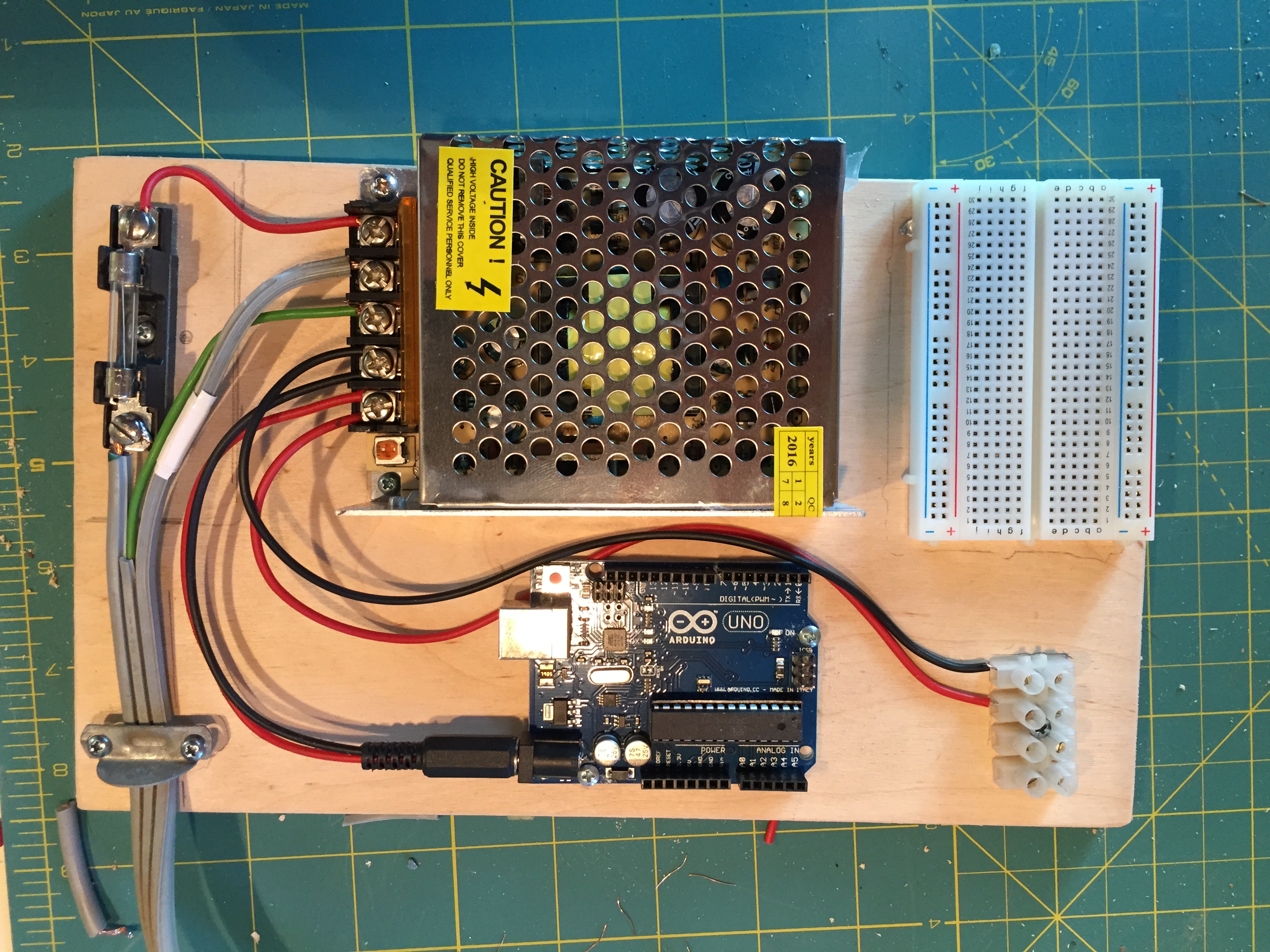 |
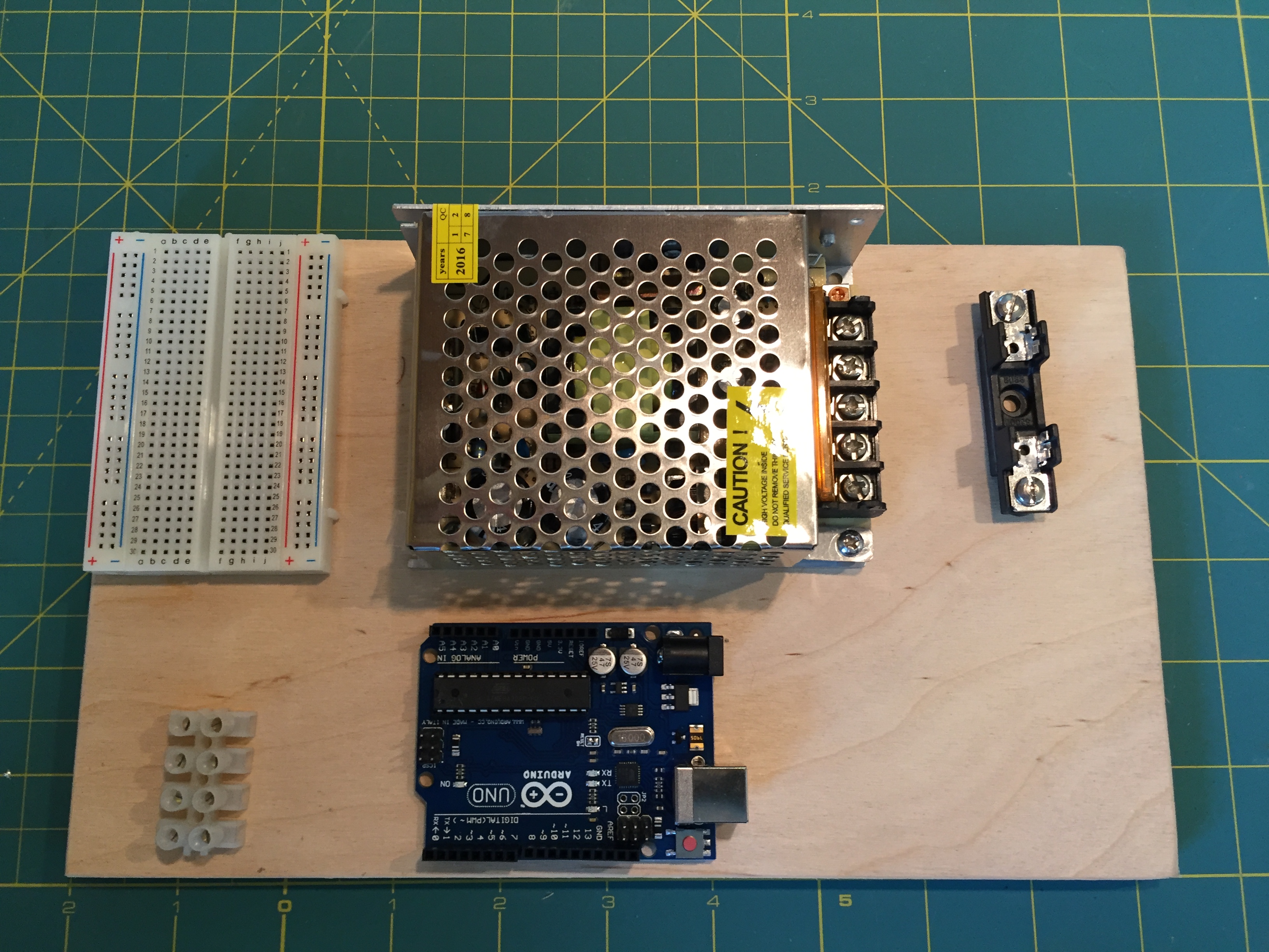
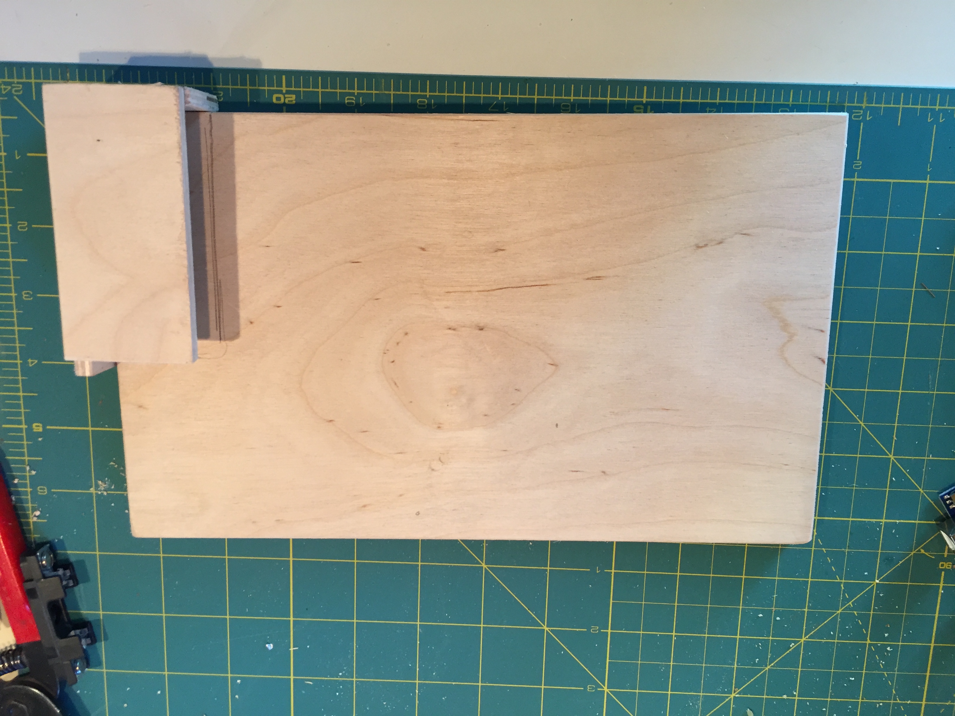
| Layout the components as a shown above. From top right are: Breadboard, 5V 8A power supply, fuse holder. From Bottom right: I/O connector, Arduino | Above is the board with power wiring completed. Identify and mark the AC neutral and hot leads. The hot lead gets a fuse. We chose 4A fuse. |
 |
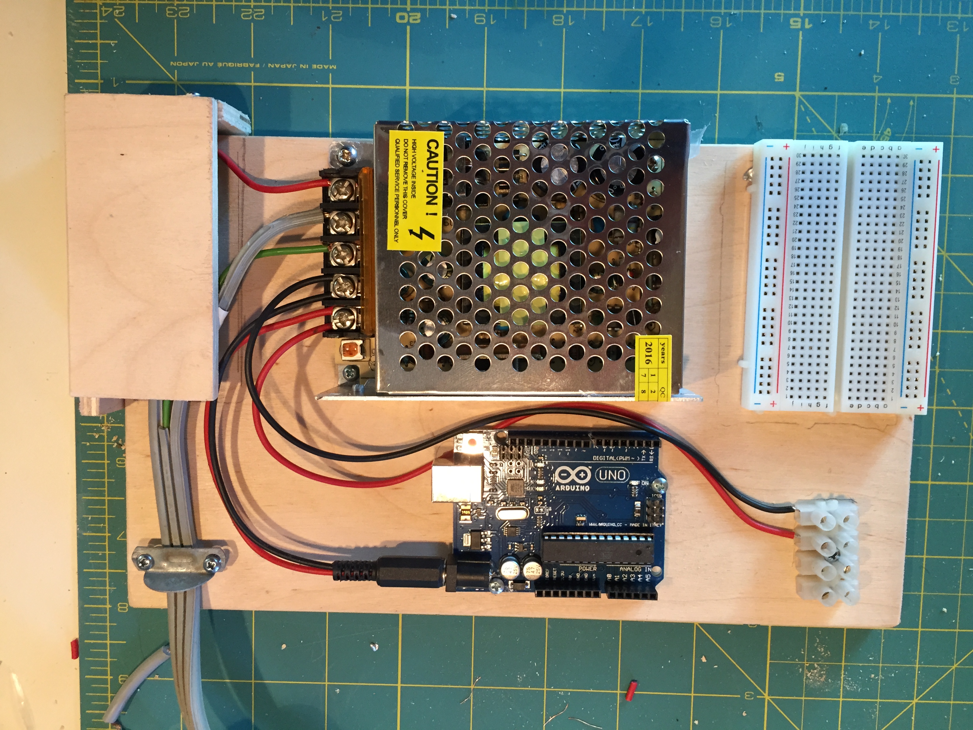 |
| Above is the board with the fuse guard. | The completed board. A guard is supplied to prevent accidental contact with the fuse, which has 120 VAC exposed. |
| The bread-board allows additional components to be connected to the Arduino. For greater I/O connections, use a bigger connector block. | |
| To continue your education on Pixel lights, I suggest your next two stops are at a great web-site, Tweaking4all.com. The systems basics are at this link. | |
| Once you get your pixels to display, the same site explains how to program your Arduino here. It can be confusing to differentiate between the Neo-Pixel and the Fast-LED methods. As a beginner, I suggest the Neo-Pixel approach. If you follow the link above, the author offers cut and paste code to get you started with various effects. | |