CASE STUDY 31:PV MODULE LEAD PLACEMENT |
|
|---|---|
I have observed in the last few years that more and more module manufacturers are placing module leads at both long edges of panels instead of at one short edge. See below for examples. Also, PV manufacturers are providing shorter and shorter leads on their panels. There are some serious problems with this trend. |
|
Click any image for a larger version. Last update January, 2024. |
|
Short edge lead placement |
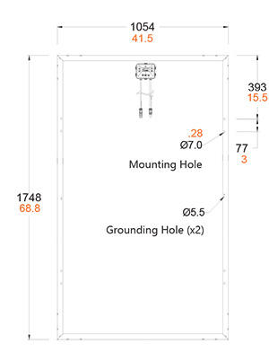
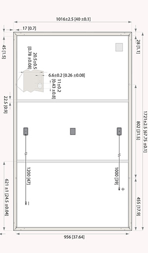
Long Edge lead placement
|
There is another trend that impacts how this lead placement affects the actual wiring of these PV modules. That is the trend towards requiring module level power electronics (MLPE). MLPE used to be optional and generally implemented first for micro-inverters and then later for optimizers (Solar Edge, for example). |
|
As of this writing I am pretty sure all building jurisdictions require module level rapid shut-down on any roof-top installation. To achieve MLRSD function requires that any roof-top installation have some type of MLPE under each and every panel or every two panels. |
|
What perplexes me is that connecting MLPE is more difficult to do with long-edge lead placement. The plus and minus leads from each module need to connect to one device, the MLPE, but it is so much harder to do if the leads come from opposite sides of the panel. |
|
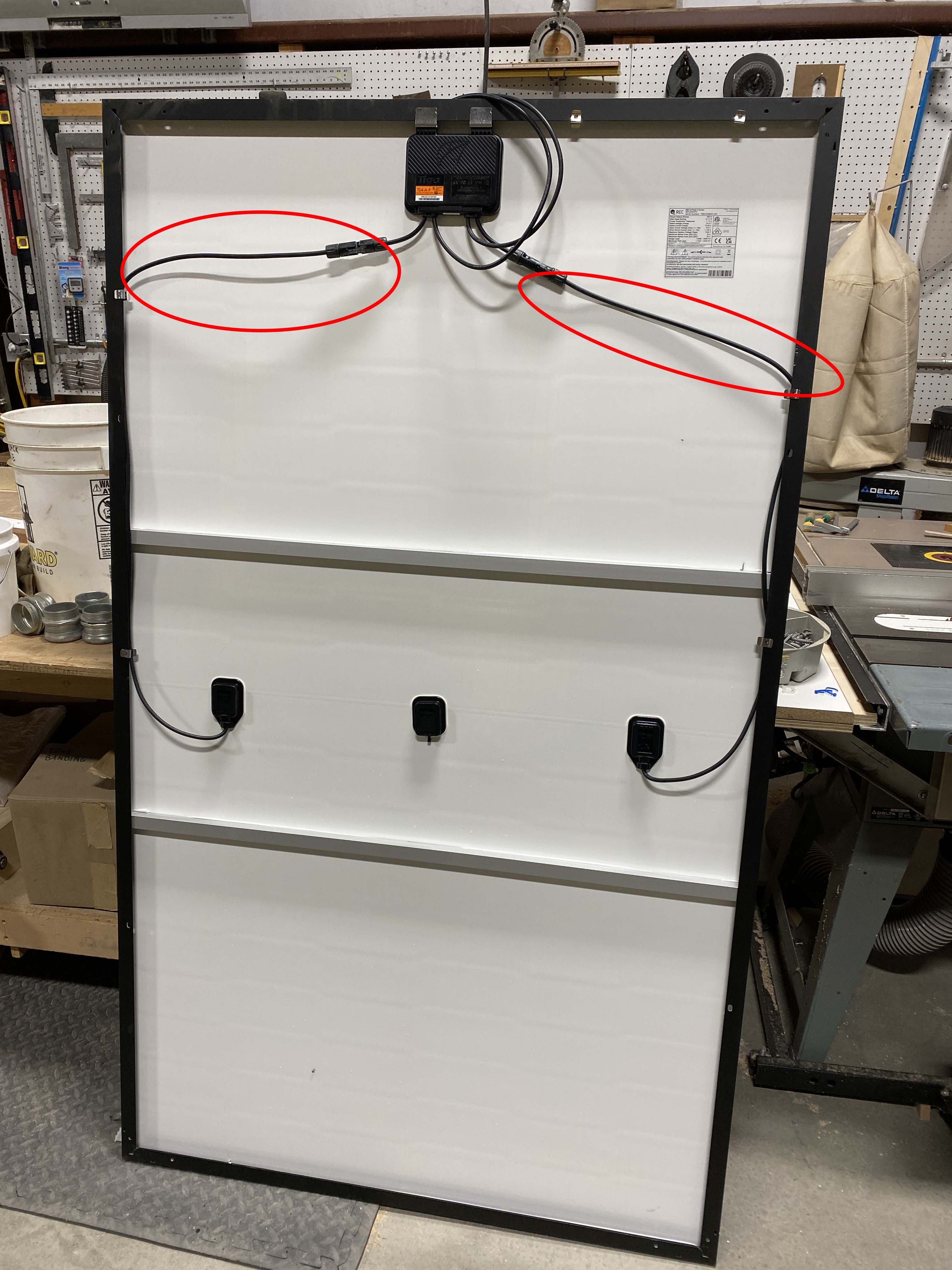
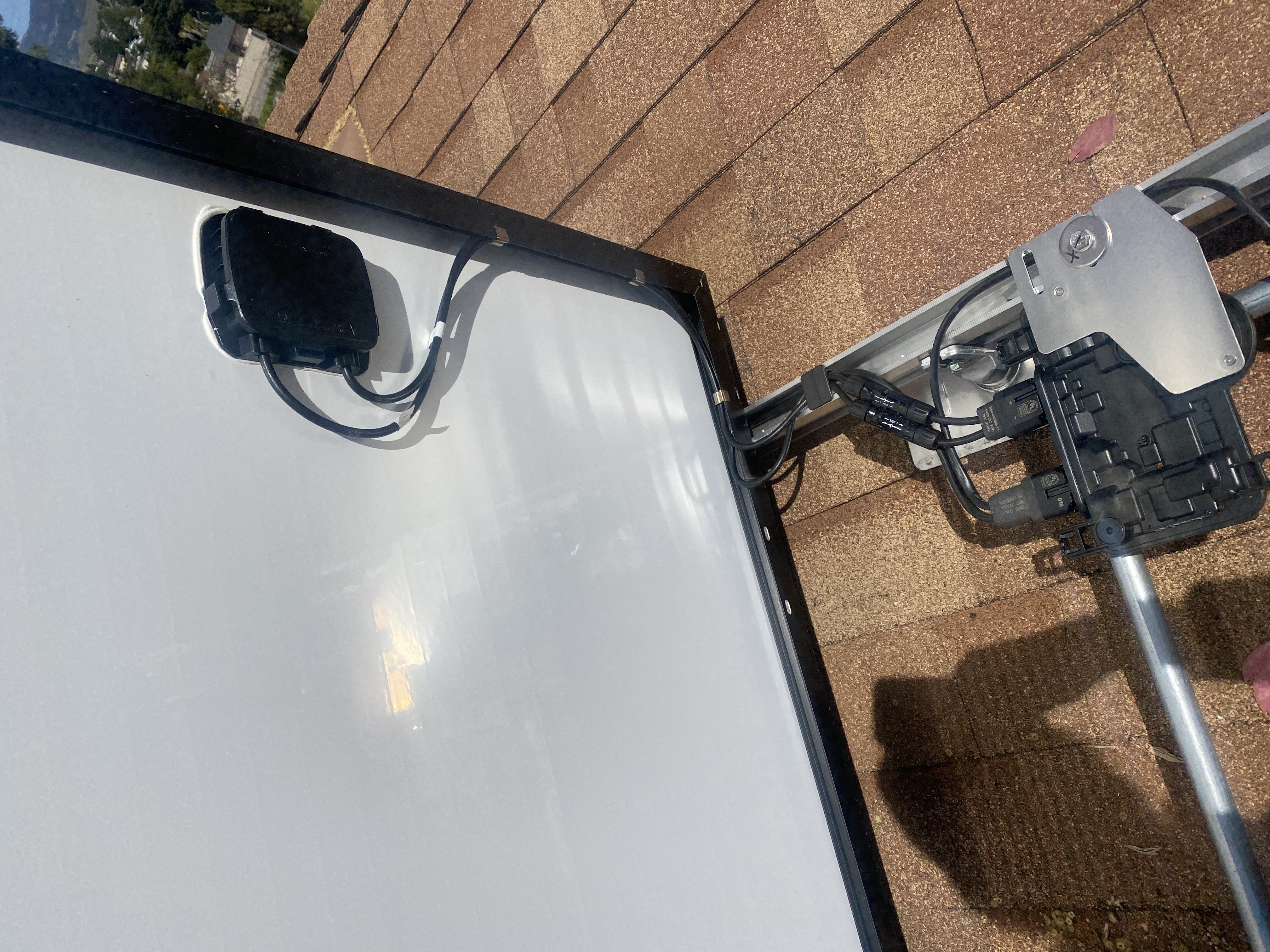
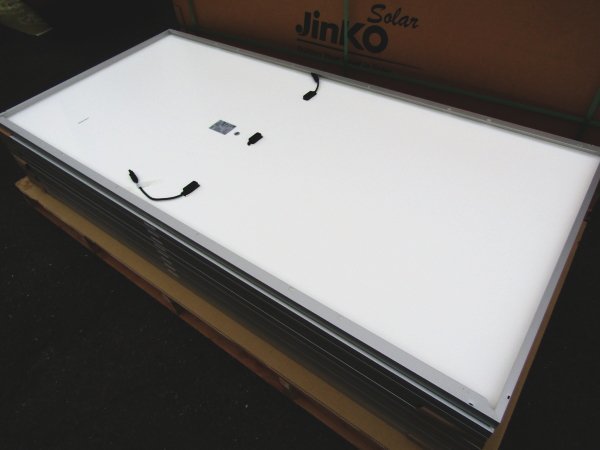
| Installing MLPE with long-edge leads is possible if the leads are long enough. It is hard to do if the leads are not long enough. And the trend is for leads to be made shorter and shorter, making this a bigger problem. Below is a photo of two panels with frame-mounted MLPE. One is a Jinko JKM400M‐72HL‐V and the other is an REC 365NP2. The goal is to support the PV leads as much as possible to prevent the leads form becoming damaged and presenting a safety hazard. | |
Jinko JKM400M-72HL-v with frame mount MLPE |
REC365NP2 with frame mount MLPE |
| Note the Jinko panel has leads long enough (1400 mm) to allow the installation of the frame mount MLPE with leads supported for most of their length. However the REC has leads that are too short (1200 mm) to allow this, making it much more likely the leads will sag onto the roof-top. Allowing leads to come adrift is a big safety problem and leads to inferior installations. | |
| Contrast the long-edge panel lead to MLPE scenario with installing short-edge lead panels with MLPE. In the photo below are Mission panels connected to Enphase micro-inverters. | |
Mission MSE325SR8K with Enphase IQ7+
|
|
| The installation above is using the "hinge" method we developed. What this means is the panel is brought to the roof and set on-edge against the previous panel installed. One installer supports the panel in a vertical orientation while another connects the leads. The goal is to connect the leads so that as the panel is hinged down, the leads cannot be pinched and cannot droop onto the roof when the panel is in place. The short-edge lead placement makes this possible. This does require some planning so as to place the micro-inverter the correct distance from the hinge point. Once the location is known, the installation proceeds quickly and efficiently with a good finished product. See this article for more details on our hinge technique. | |
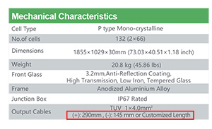
Another factor that compounds this is the trend towards providing shorter and shorter leads. Jinko panels depicted above have leads 1400 mm in length. The REC panel depicted above has leads that are 1000 and 1200 mm. As we have seen, 1400mm is enough, 1200 is not. I found the newer Jinko JKM360M-6RL3-B has leads 290 mm (+) and 145 mm (-). I can't imagine how you install one if these without making two jumpers for each panel with the attendant expense, hassle and increased likelihood of connection problems. See image below from the data sheet for the JKM360M-6RL3-B. |
|
|
|
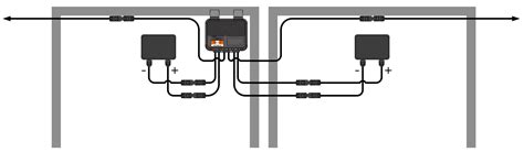
What is even more perplexing are the MLPE devices that are designed to connect to two modules. How in the world are installers supposed to avoid a rat's nest of wiring while trying to connect one of these devices as shown below? The drawing below depicts the device with two short-edge-leaded modules, which would be difficult enough to manage. However with two long-edge-leaded modules how can the right-most lead on the right most panel get to the MLPE? See two examples below. |
|
Tigo TS4-A2F wired with short-edge leaded panels. |
|
Tigo TS4-A2F wired with long-edge leaded panels. |
|
I think PV module manufacturers need to hear about these types of real-world problems and correct these problematic trends. |
|