What's Wrong With the SMA 40 Series Inverter? |
|
| Welcome to our continuing "What's Wrong" product reviews. In these articles we reveal design and construction defects of solar products. We don't mean to imply that these products are entirely flawed, but we do expose significant defects in the products that the wary consumer should be aware of. Click on any photograph for a full-sized view. | |
| Product: | SMA America 40 Series inverter. Sizes range from 3.0 to 7.7 kW. |
| Defects | Description |
| 1. Integral DC disconnecting means located in wrong chassis. | Every complex electronic assembly carries the possibility of equipment failure during its service lifetime. Manufacturers need to make the products so they can be safely serviced. SMA fails to do this with this line of inverters, as described below. |
 |
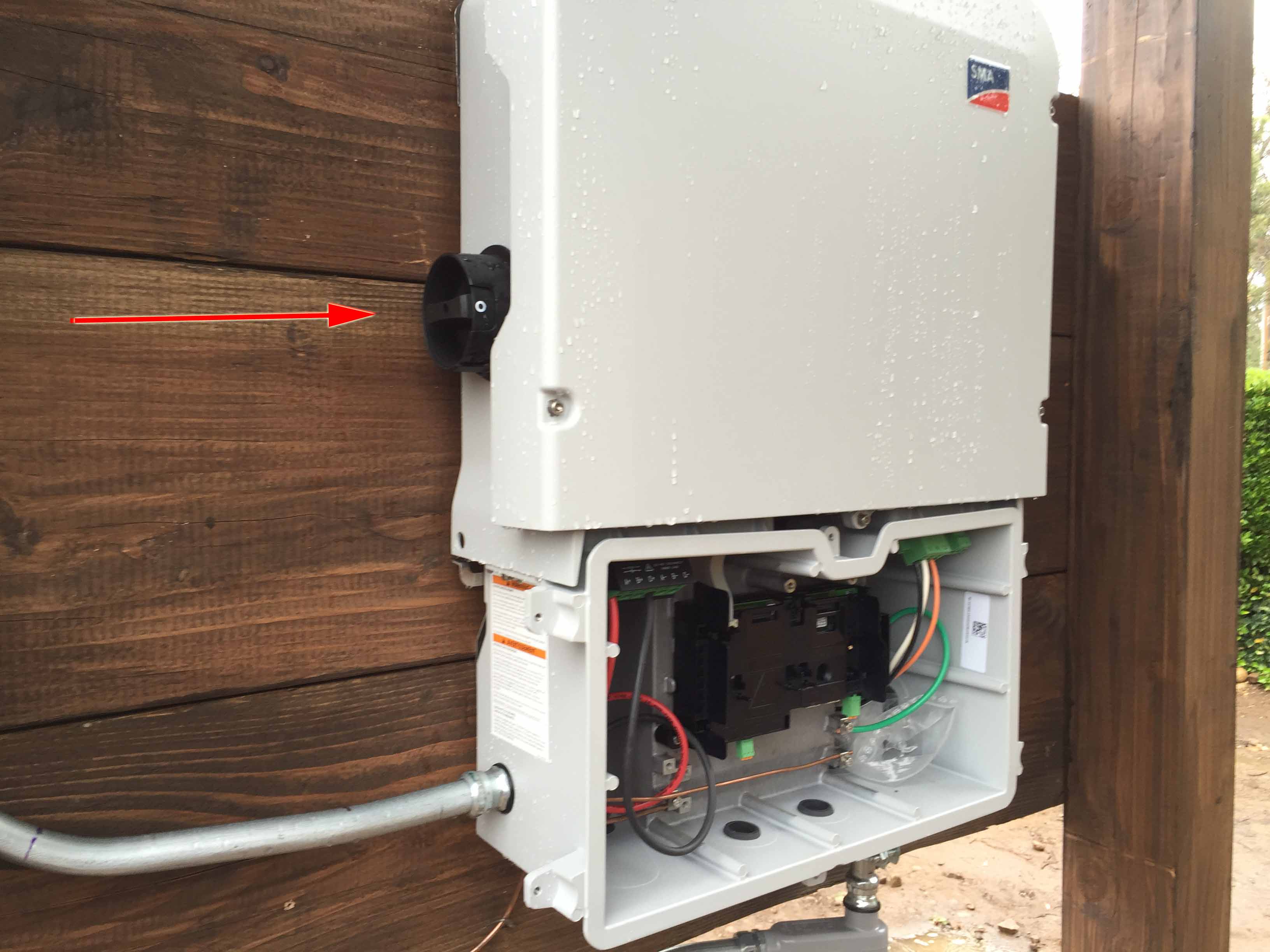 |
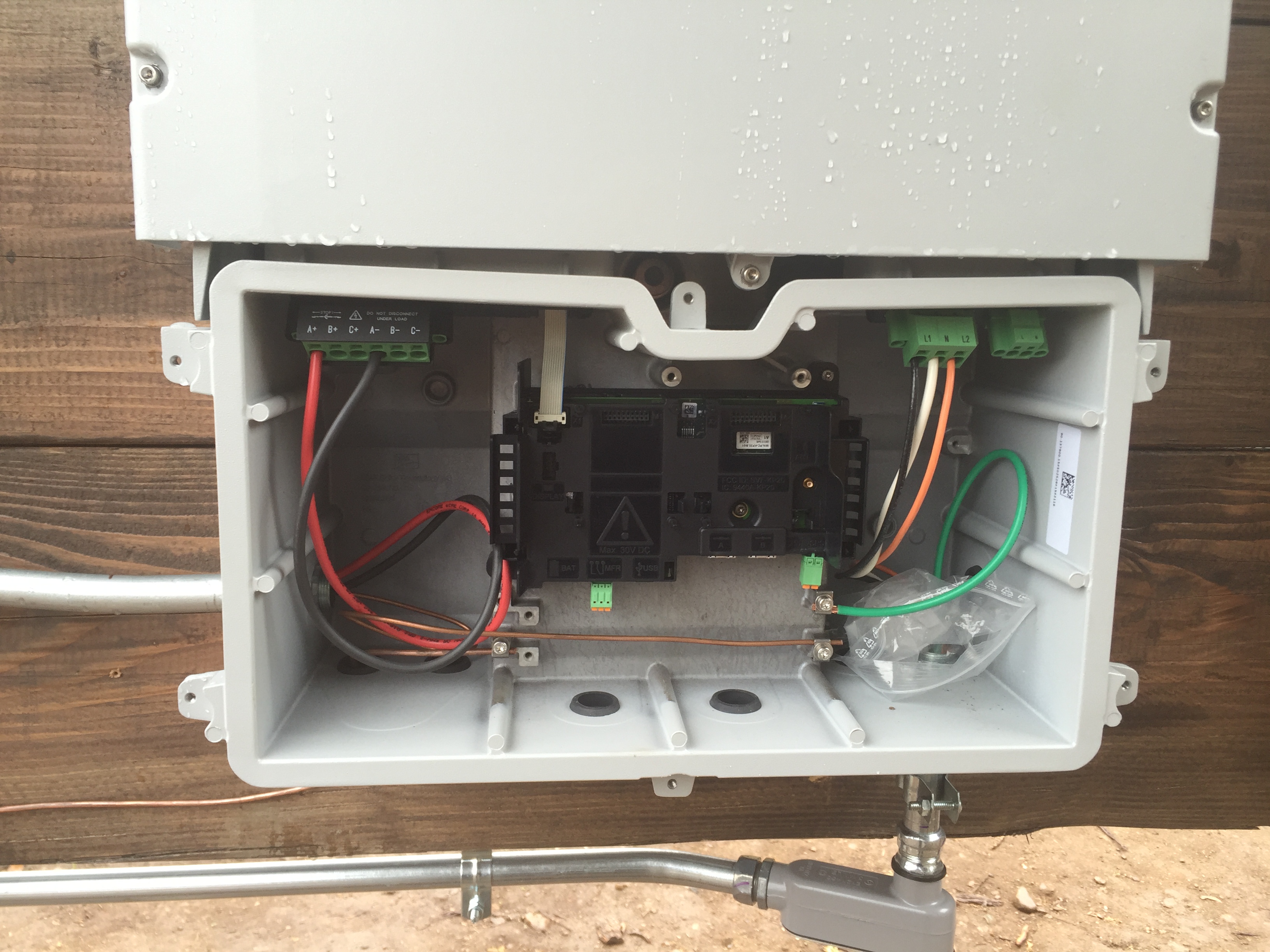
| DC power from solar panels contains voltages that may be fatal if contacted. Electrical equipment needs to be designed such that these voltages can be disconnected prior to service. Above is a photograph of the DC connection section of an SMA 40 series inverter. | Above is photograph of the location of the DC disconnect for the 40 series inverter. Note that it is in the upper, electronics section of the inverter. This is the section that contains the complex electronics that may fail. This is the section that will need to be replaced if that occurs. In order to replace this section, the AC and DC terminals need to be disconnected. With the available equipment, there is no safe way to de-energize the dangerous DC voltages without installing a separate, expensive DC disconnecting means. |
 |
 |
Above is a photograph of the DC connector for this product. The connector is insulated but the manual says touching it while energized is unsafe. See next panel.
|
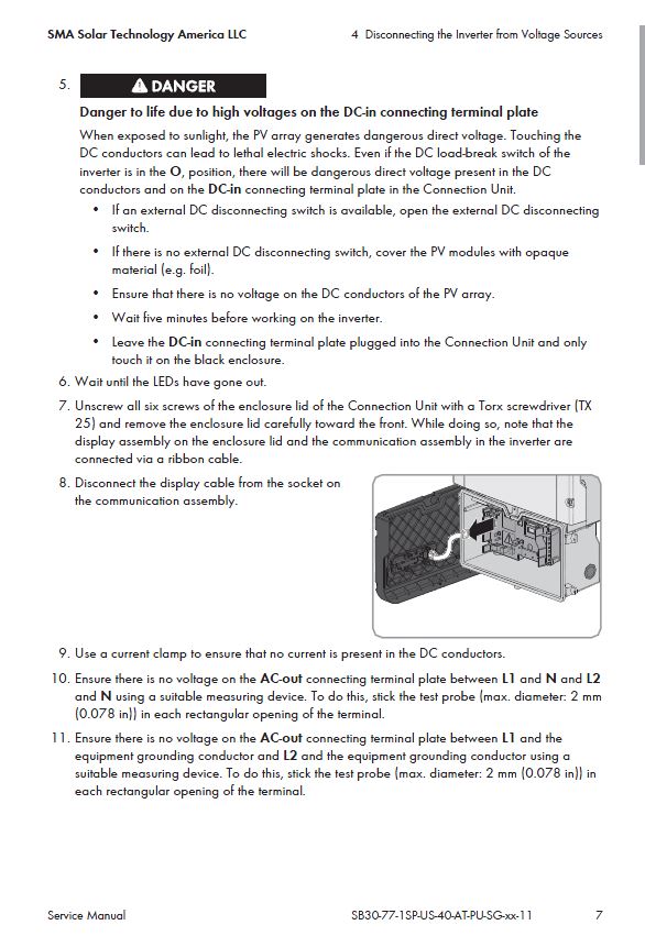
Above is a page from the service manual for this product that indicates the recommended method for rendering the DC connector safe. Note in bullet point 2 it indicates that the service personnel should cover the solar panels with an opaque covering. This is entirely impractical for these reasons: 1. Assuming by 'foil' they mean tarps, most locally available tarps are not opaque. 2. Solar panels are often in high places and cover large surface areas. Placing tarps is dangerous and difficult.3. One gust of wind can uncover the solar panels and expose the installer to these dangerous voltages. Relegating this service work to after dark is impractical and should not be considered as a solution for obvious reasons. |
 |
 |
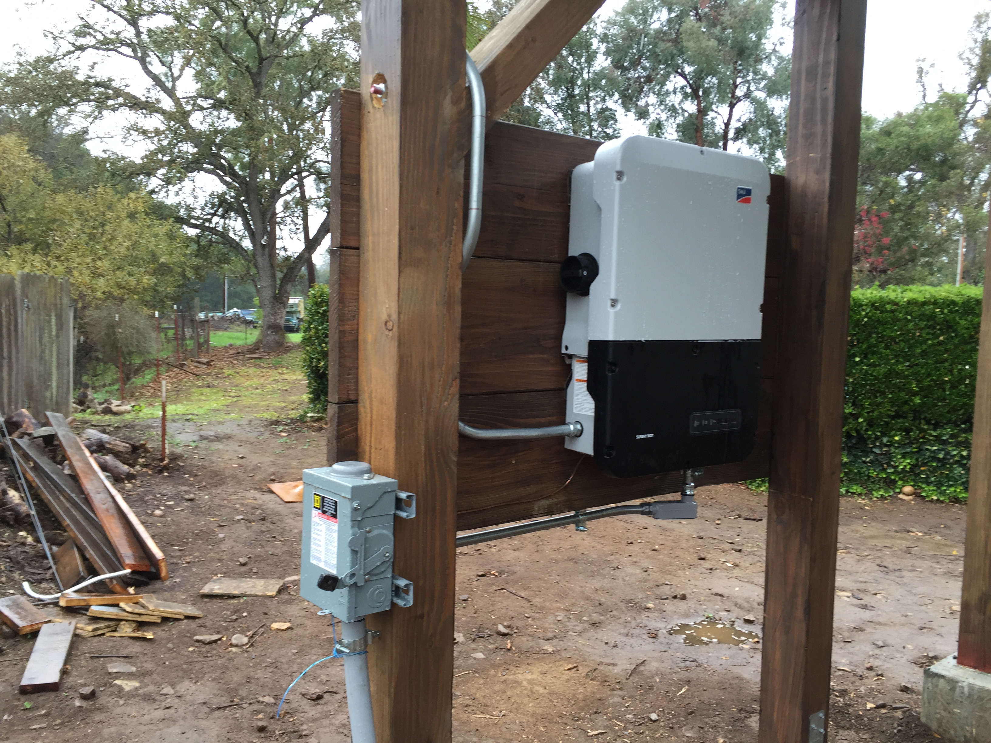
| Above is a photograph of an installation using this product. An AC disconnect was installed because the circuit breaker used to de-energize is not within line-of-site. This installation should be retrofitted to add an external disconnect as depicted in the next panel. | Above is a photograph of an external disconnect with adequate rating for the DC voltages encountered. These disconnects are about $250.00 retail. Adding one of these will increase the footprint and cost of an installation. Granted, rapid shutdown compliance may eliminate the requirement for these disconnects from future projects, but can one safely rely on a remote electronic disconnecting means when personnel safety is involved? Furthermore, it appears ground-mount and shade-structure mounts will not require rapid shut-down, so that work-around is not available for these inverters. |
| 2. There are no explanations in the manual about the display values. | The 40 series inverter includes a digital display of the operating parameters for this inverter. Nowhere in the manual is any explanation given for what the values mean. I understand what the values indicate, but I can't expect a home-owner to. In order to "turn-key" one of these systems to a home-owner, I need to write a manual addendum to offer to the home-owner. The manual should be updated with this essential information. the same is true for the 22 series inverter. |
| 3. The smaller wattage inverters are over-large. | The 40 series 3 kW inverter is: 21.1 in x 28.7 in x 7.8 in The 22 series 3 kW inverter is: 19.3 in. x 20.5 in. x 7.3 in. The 40 series 3 kW inverter is a full 8" taller than the 22 series. Adding an external DC disconnect and this inverter takes up a lot of real estate. |
| Conclusion: | If you are planning on procuring one of these inverters, design your installation to include an external DC disconnect. Otherwise you are putting service personnel at undue risk. |