| What's Wrong with the Solectria PVI Inverter? | |
|---|---|
| Click on any image for an enlarged version. | |
I have two major complaints: 1. Mounting. Click here to see how we solved this problem. 2. Documentation. |
|
Update 8/4/15: I spoke with Charlene Langland of Solectria. Ms. Langland is very professional and as helpful as she can be. She is lacking final answers from the engineering department. She is hoping to set up a conference call with them soon. Here is what I learned given the information available to date: 1. The residential PVI inverters do not have a separatable wiring box. I pointed out this meant any installation required an outboard DC disconnect, adding to the cost and complexity of any installation. Solectria does have an outboard remotely activated disconnect that might be a solution to this. The cost will have to be added to any installation. 2. The mounting bracket has been deemed adequate. She does not know if seismic testing has been performed (I will continue to disagree with this point, see below). 3. The inverter cannot be mounted on a flammable surface. The inverter gets very hot, as high as 90 degrees C. (I hope I heard this wrong. This could create third degree burns on skin, see this link or this). No solution is offered for mounting on wood-sided surfaces, interior or exterior-- if your surface is wood, don't buy Solectria. (After the conversation I wondered about the inevitable build-up of leaf debris if trees are anywhere near the inverter. I will be asking about this). 4. The resolution problems and incorrect information in the online manuals have supposedly been corrected. I checked and found this not to be true.
|
|
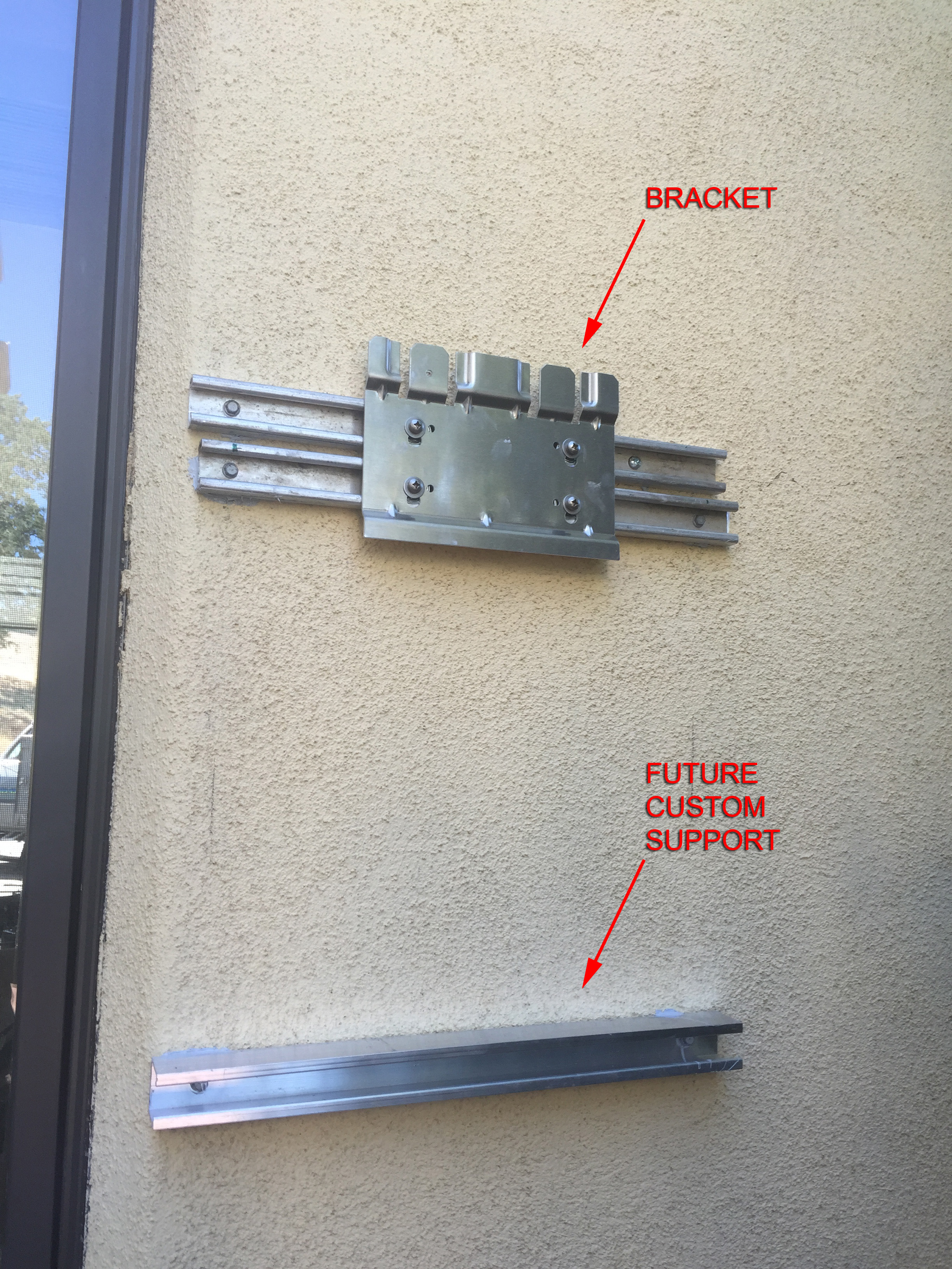
| Mounting Problems: The PVI series inverter, especially the larger units, have inadequate mounting brackets. The 65 pound inverter rests on a bracket about 4 inches wide. There is no way to lock the inverter to the bracket, in spite of the fact that the manual calls for "lock-nuts" that don't appear in the specified drawings. There is no support under the lower 90% of the inverter, including the wiring compartment. See below for details. | |
 |
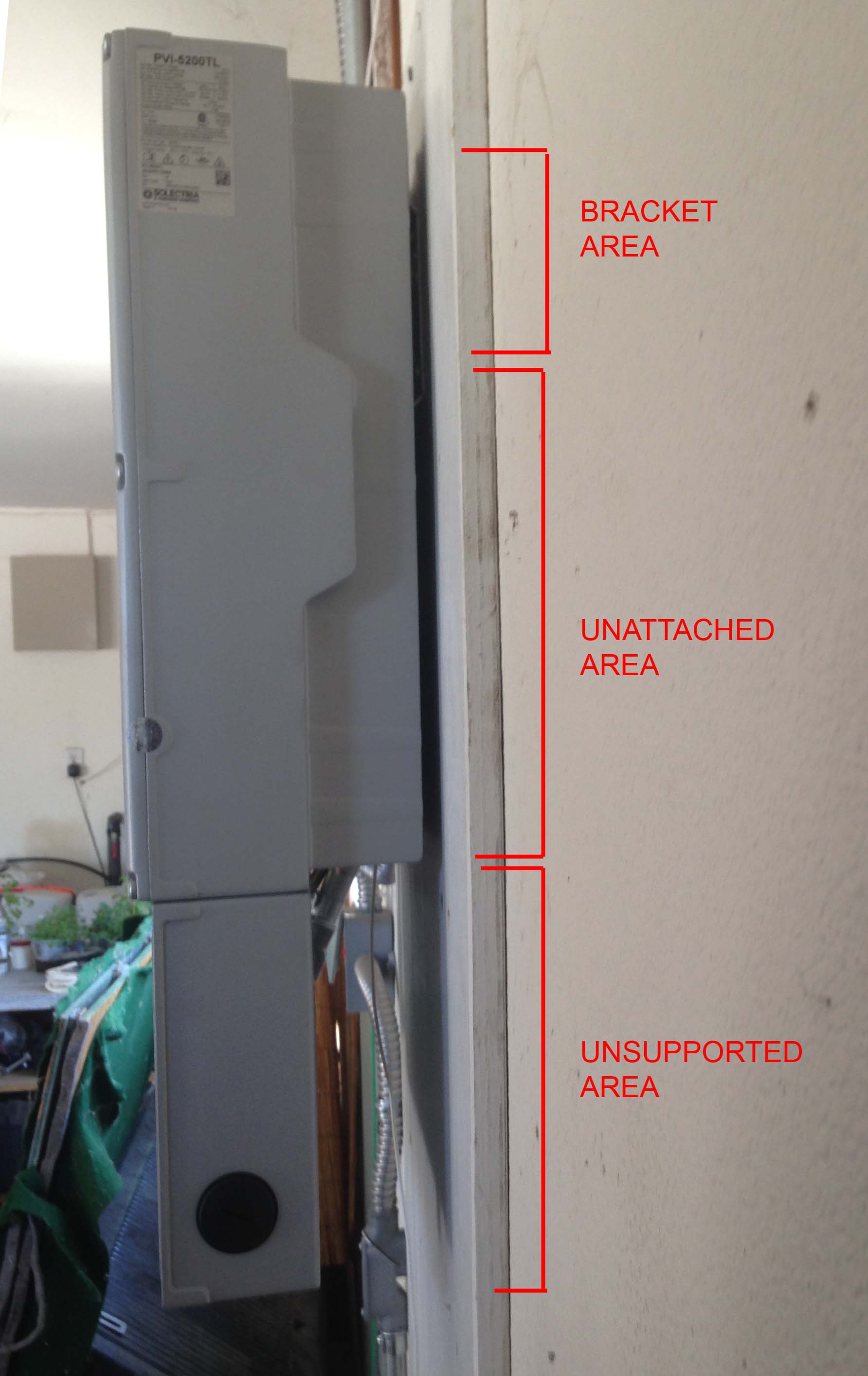 |
| Above, note how narrow the mounting bracket is. The inverter rests on this bracket with no mechanical fasteners. | Above, note how small the attached area is. There is no attachment below the bracket. |
 |
 |
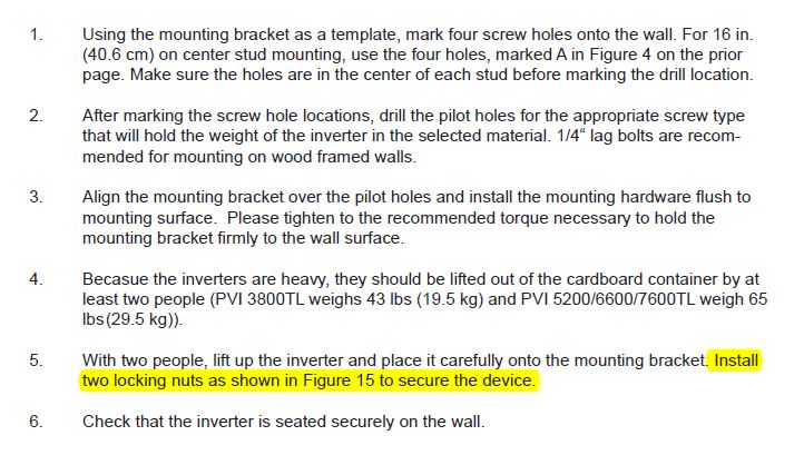
| Above are the instructions from the manual. Note the referral to lock nuts as shown in figure 15. | Figure 15. Do you see any lock nuts? |
|
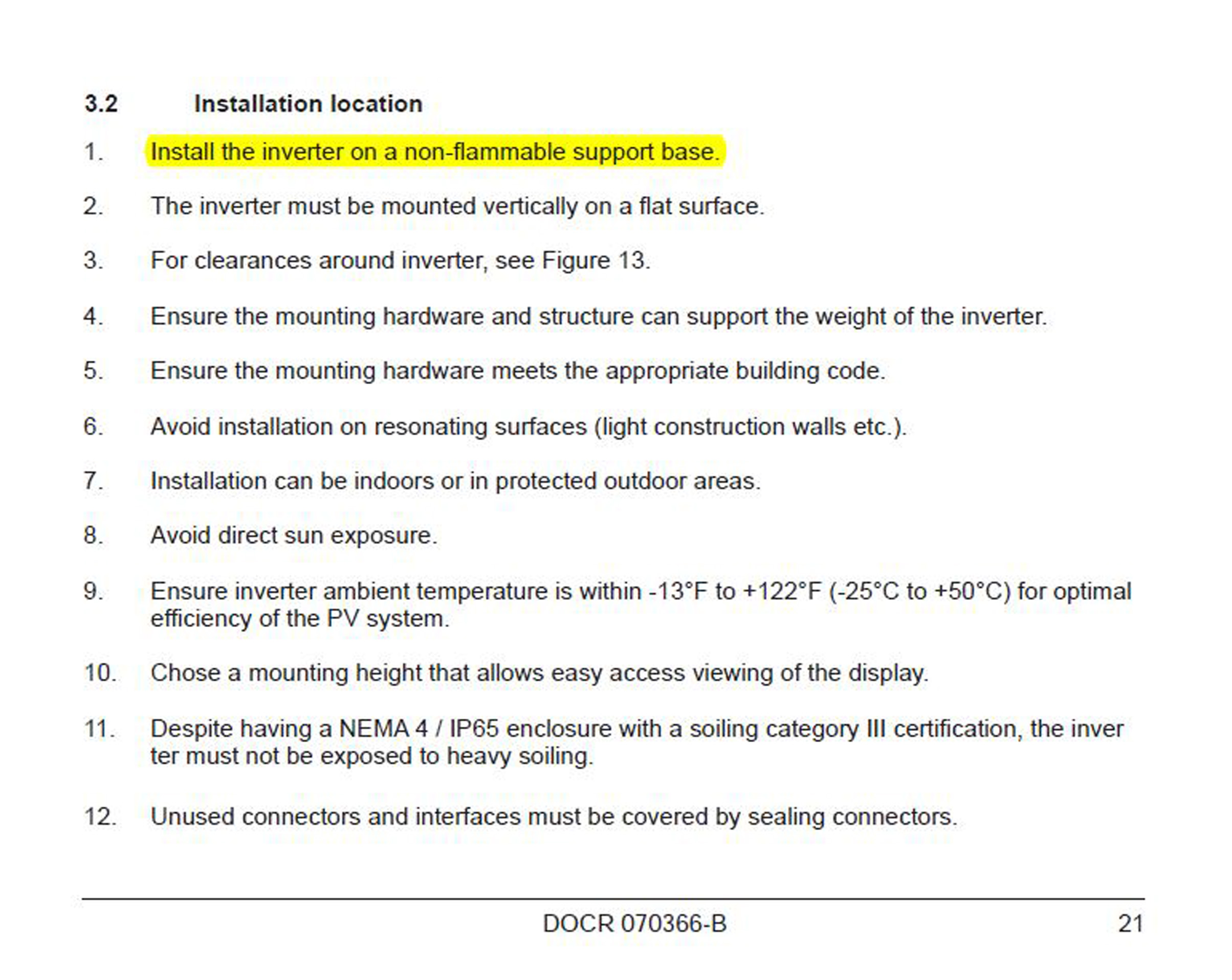 |
| Here is another problem. The top half of the inverter contains the electronics. In the event of a failure of the electronics, the top half is removable, leaving the bottom half, the connection box. With the top portion removed, what will hold up the bottom section? The conduit? What if you are using EMT or flex? The box will flip and/or sag. Note there are several inches of space between the wall and the connection box. What will happen during minor seismic events? The entire mass of the inverter will be jerking on the conduit, causing the potential for damage and high voltage arcing. This is a dangerous situation. | Note the section in the manual above. The inverter is required to be mounted on a "non-flammable" surface. Does the inverter get that hot? This means that if we are mounting on wood siding we have to obtain sheet metal, sheet rock or some other nonflammable material to put behind the inverter. If mounting on sheet rock and the location of studs does not allow screwing to two of them, then we can't use plywood. This does not seem right. |
| Conclusion: This inverter mounting system is totally inadequate. There is a lack of support for the unit, there is no independent support for the connection box and no mechanical means to prevent movement of the inverter in case of a seismic event or children hanging on the conduits. This unit needs to go back to the drawing board. | |
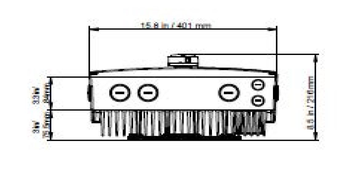
| Problem 2: Some sections of the on-line manual are unreadable. See below. | |
 |
|
| Above is a screen shot of the PDF file. Can you tell me the dimensions of this inverter? I have asked three different people at Solectria to correct this problem, starting some months ago. Still no improvement. I have also been promised DWG files and the promise has never been fulfilled. | |
| Overall Conclusion: It appears that the Solectria PVI series inverter has some serious mechanical problems. It also appears the Solectria is willing to take our money, but is not willing to improve on deficiencies with the product. I have talked with numerous people at Solectria but to date, no one has resolved any of these issues. | |