Big Sur Coast Service Upgrade |
|
|---|---|
Below are photos and drawings that attempt to explain the steps we have planned in order to remove an existing, unsafe 200 Amp service and replace it with a new 300 Amp service. |
|
The timing of the project will be tight once the power is disconnected. We want to minimize the time power is off. We also want to make the process as smooth as possible. There is a backup generator on site so we plan on connecting that up as soon as possible. That connection will not be possible until much of the new equipment is installed and wired. |
|
The project is made more complicated by the tight physical constraints posed by the existing meter closet. The client did not want to modify the structure so we had to make the installation fit into that space. |
|
| Click on any thumbnail for full-size photo. | |
Existing Service Equipment |
|
 |
 |
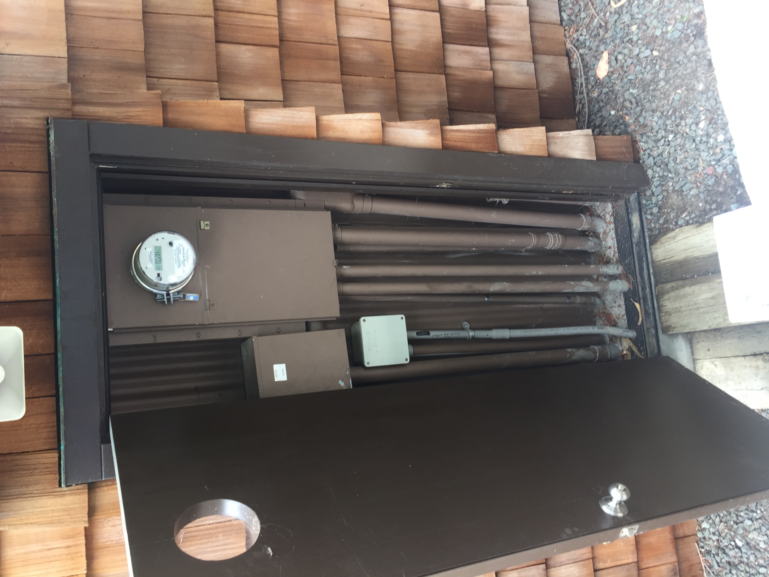
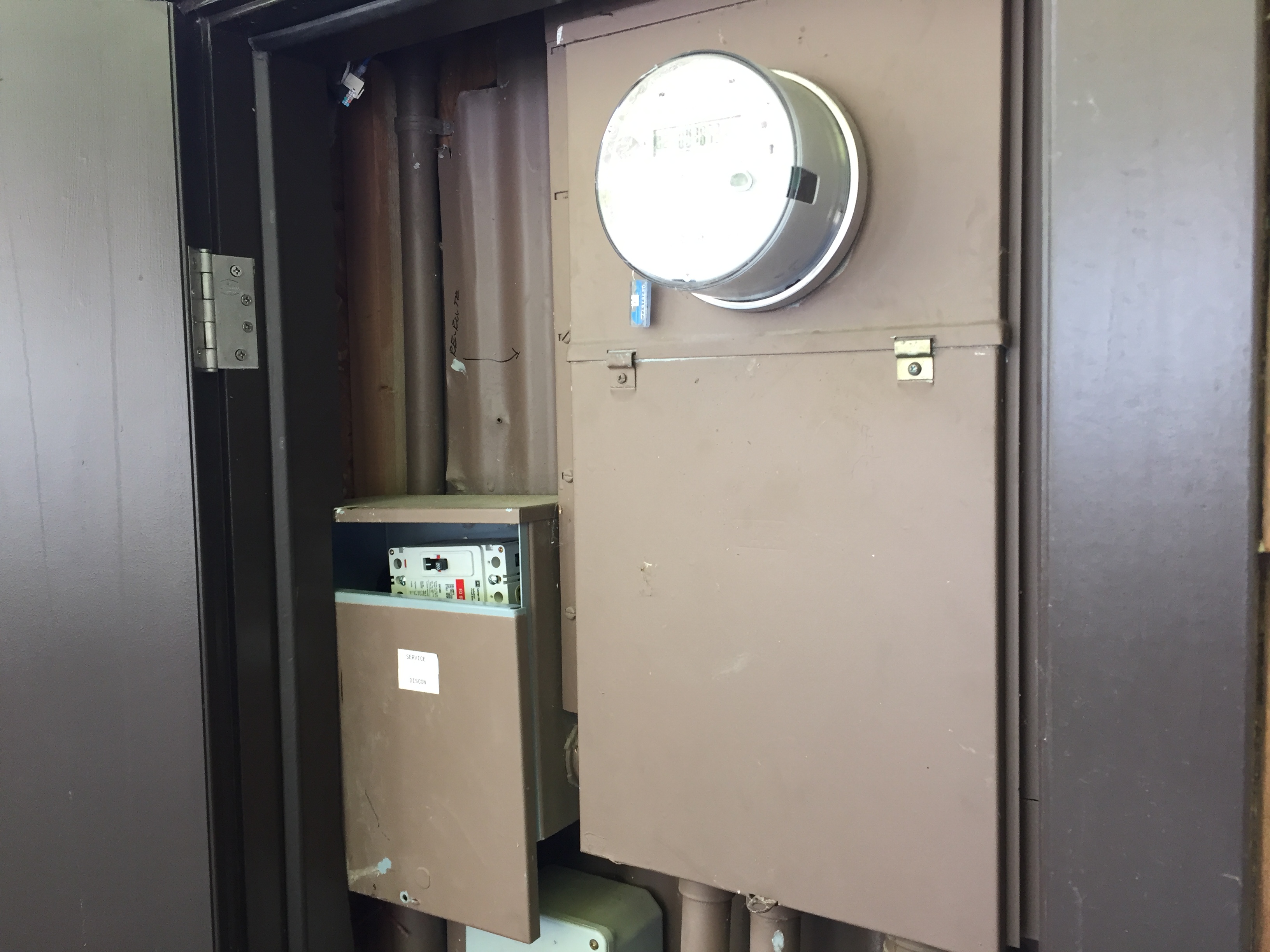
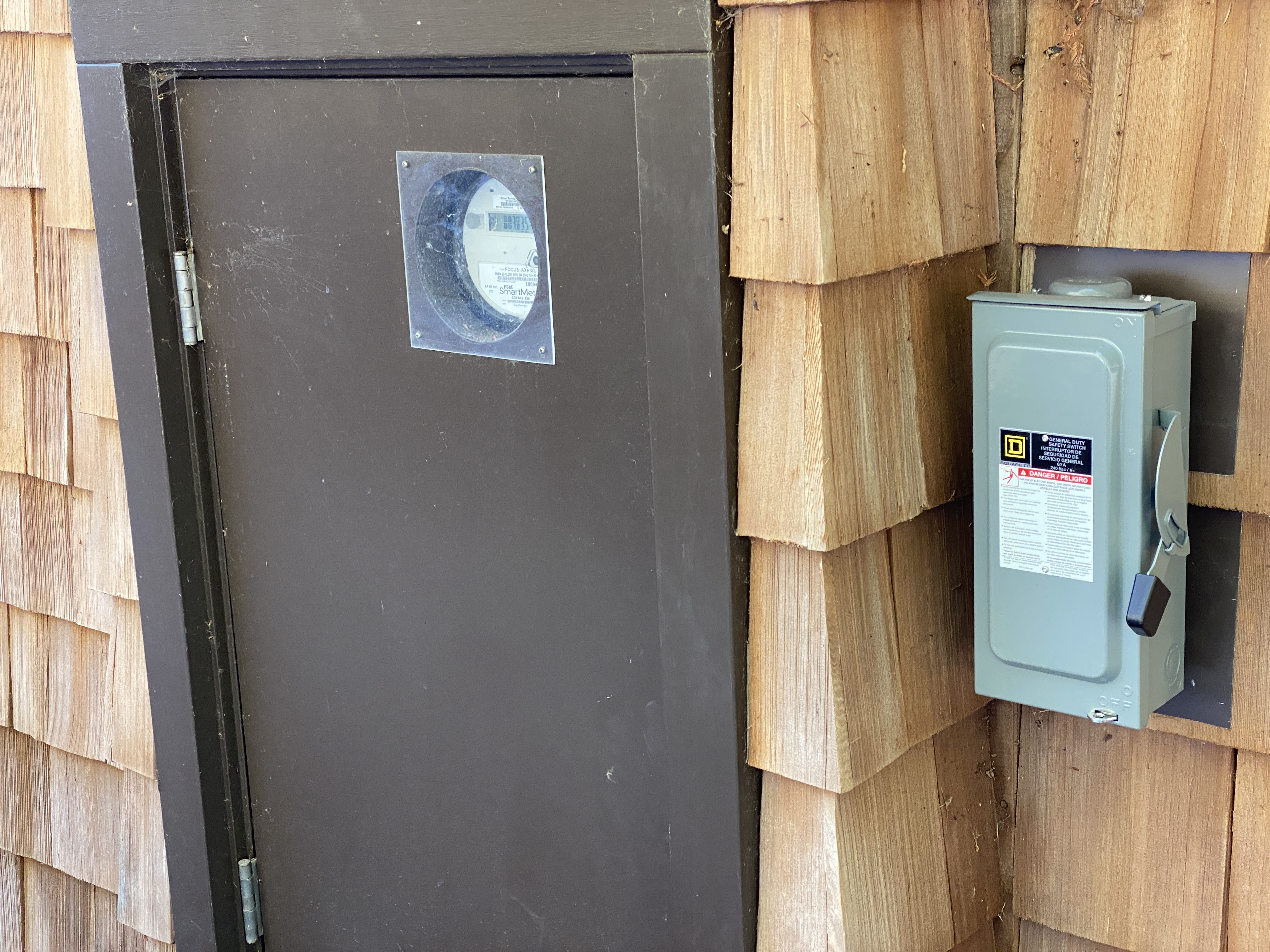
Shows existing service equipment in exterior closet. |
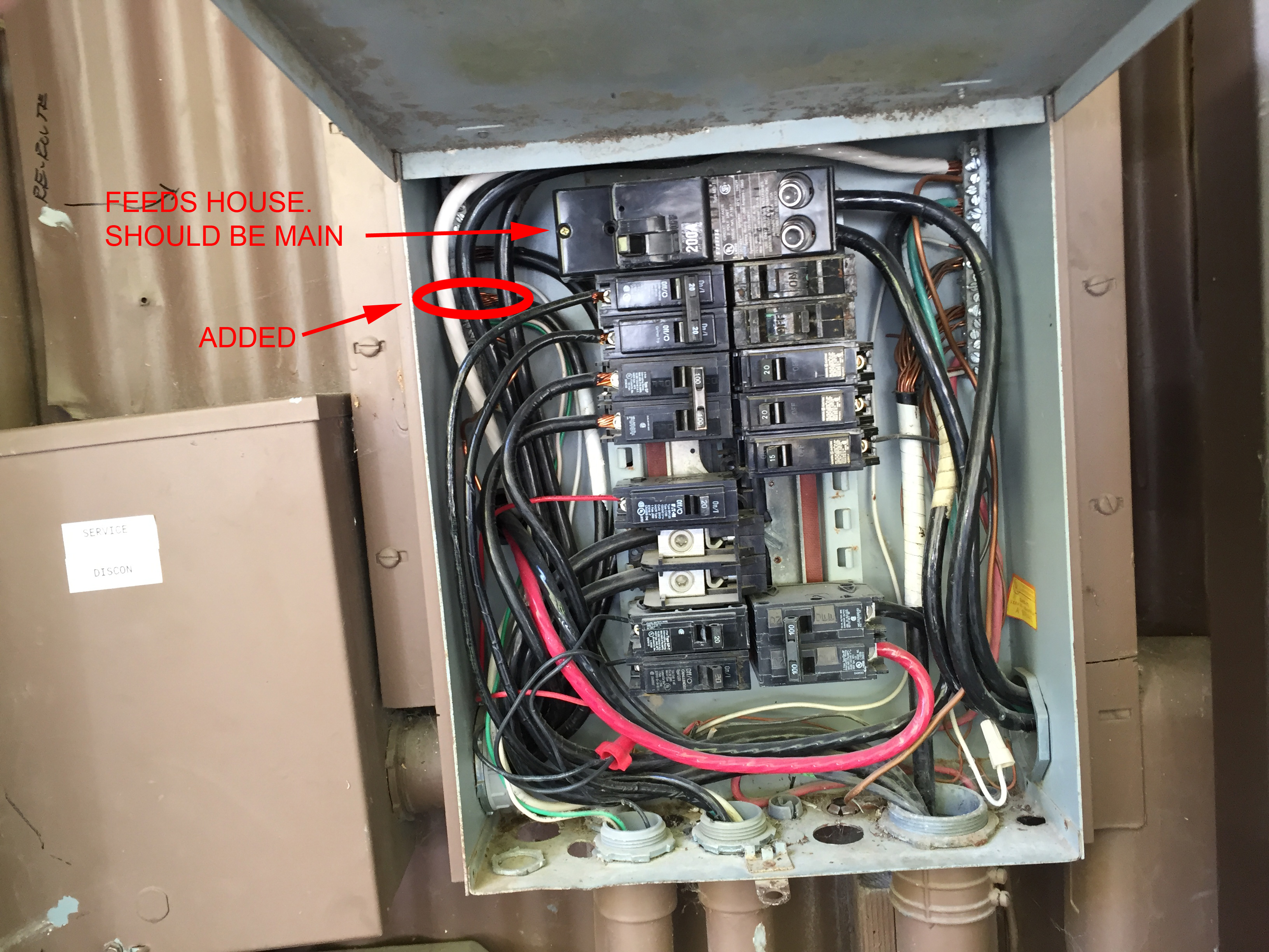
The service has been modified sometime in the past to accommodate a feed to the generator transfer switch. The factory leads from the meter socket to the main breaker were removed. The meter socket output (unprotected) is fed to an external 200 Amp main breaker. The return from the transfer switch feeds the bus and the main breaker is re-purposed to feed the house. This installation is illegal and unsafe. |
 |
|
| The main breaker can almost be accessed if you force the cover off. | |
Mock up |
|
 |
 |
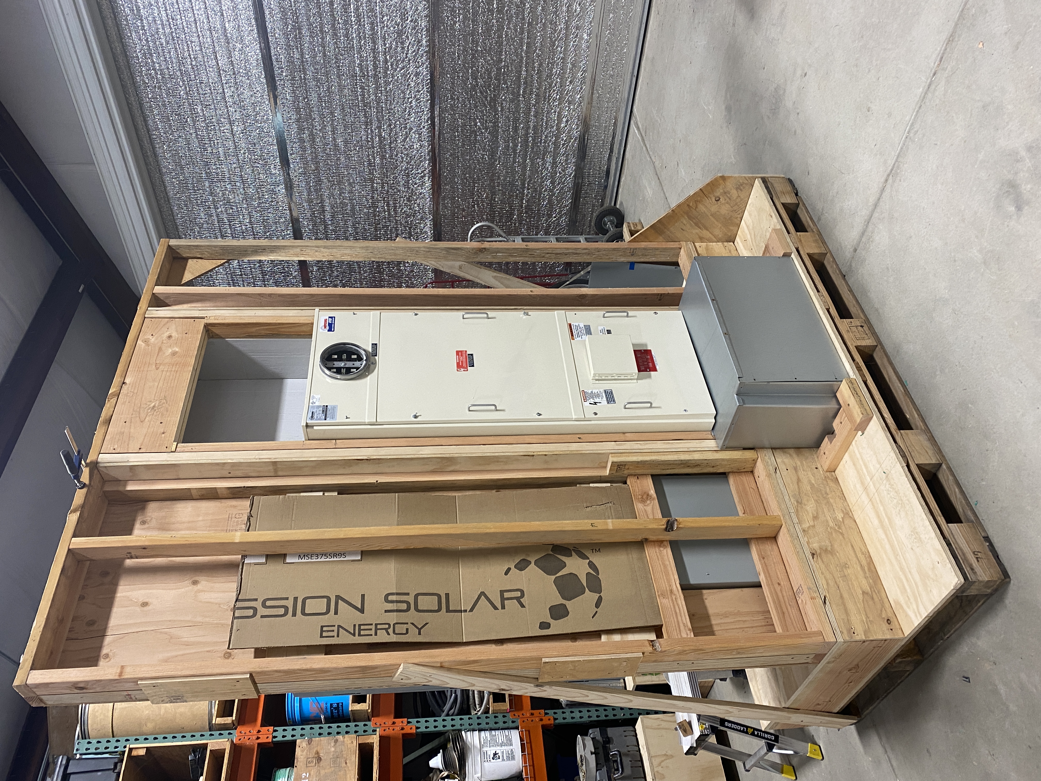
We built a mock up of the framed wall and the new equipment in our shop. This shows the exterior without exterior sheeting. A shop-made gutter below covers all wiring from conduits and routes them to proper cabinet. |
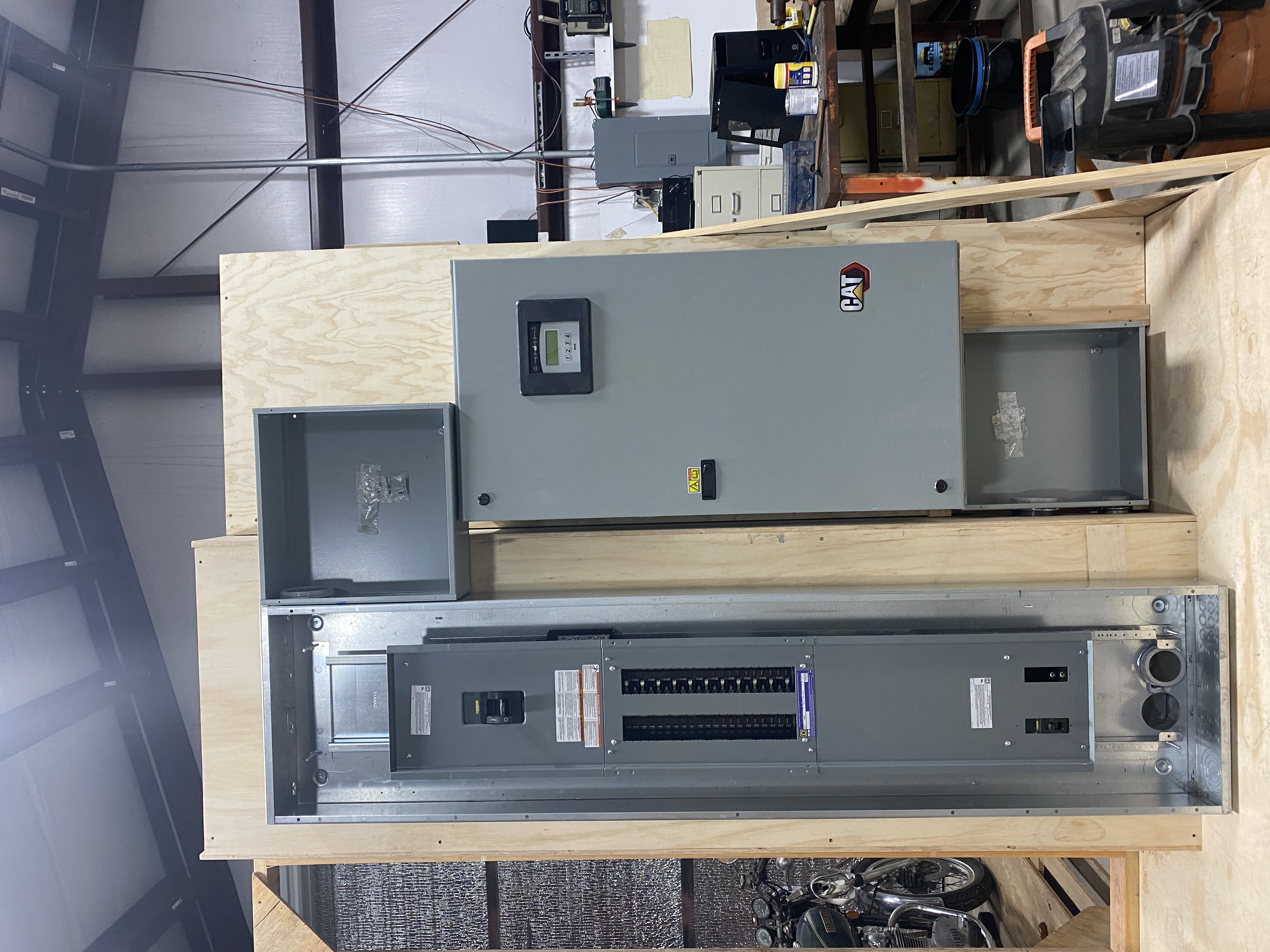
This is the interior view. The equipment is designed to disassemble in 3 major parts: Meter cabinet with framing, transfer switch on wall section and breaker panel. |
 |
|
We pre-wired the feeders to make sure we have enough cable and that all leads are pre-bent, pre-stripped and ready to install. |
|
Install Chain of Events |
|
 |
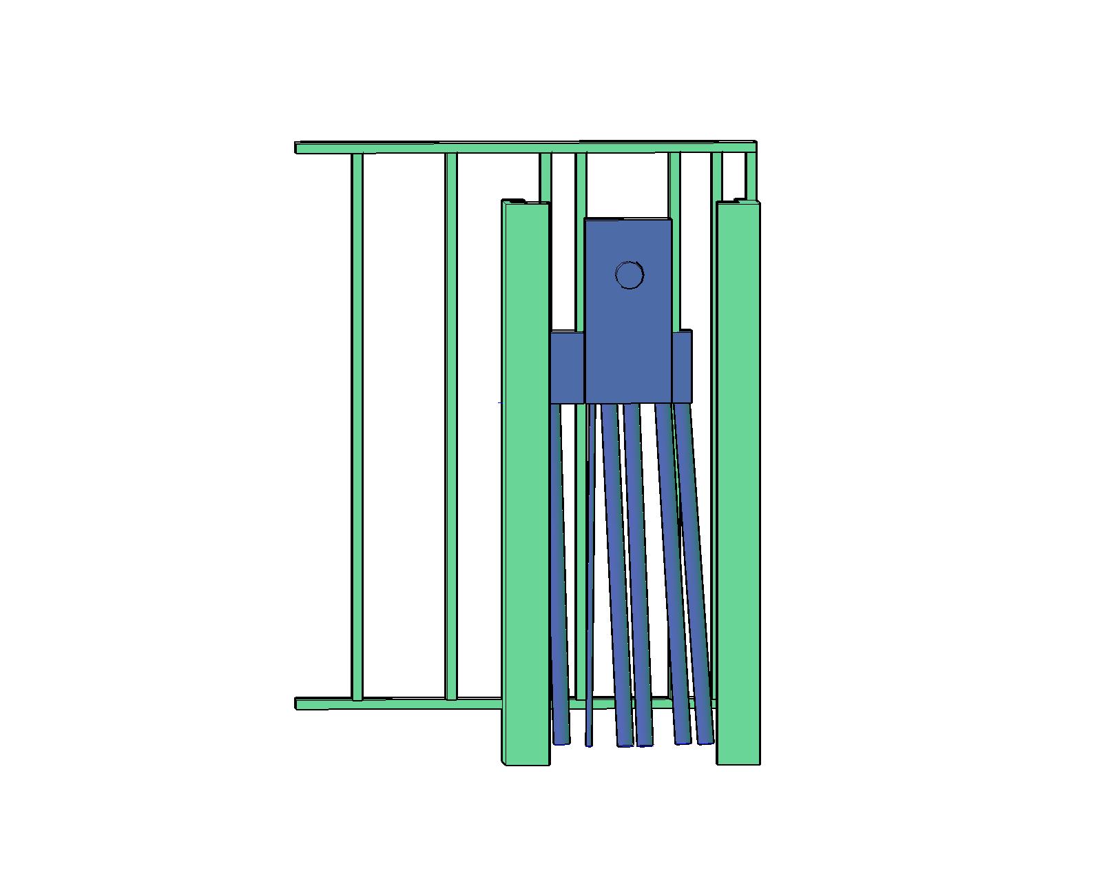 |
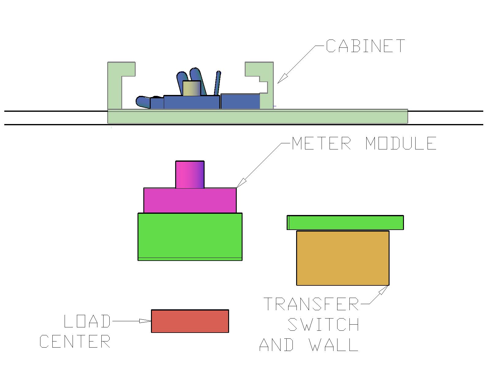
This plan view shows the exterior wall with the existing meter-can and conduits and the major components staged, ready to slide into place. |
Exterior view of the existing equipment and framing without sheeting. |
 |
 |
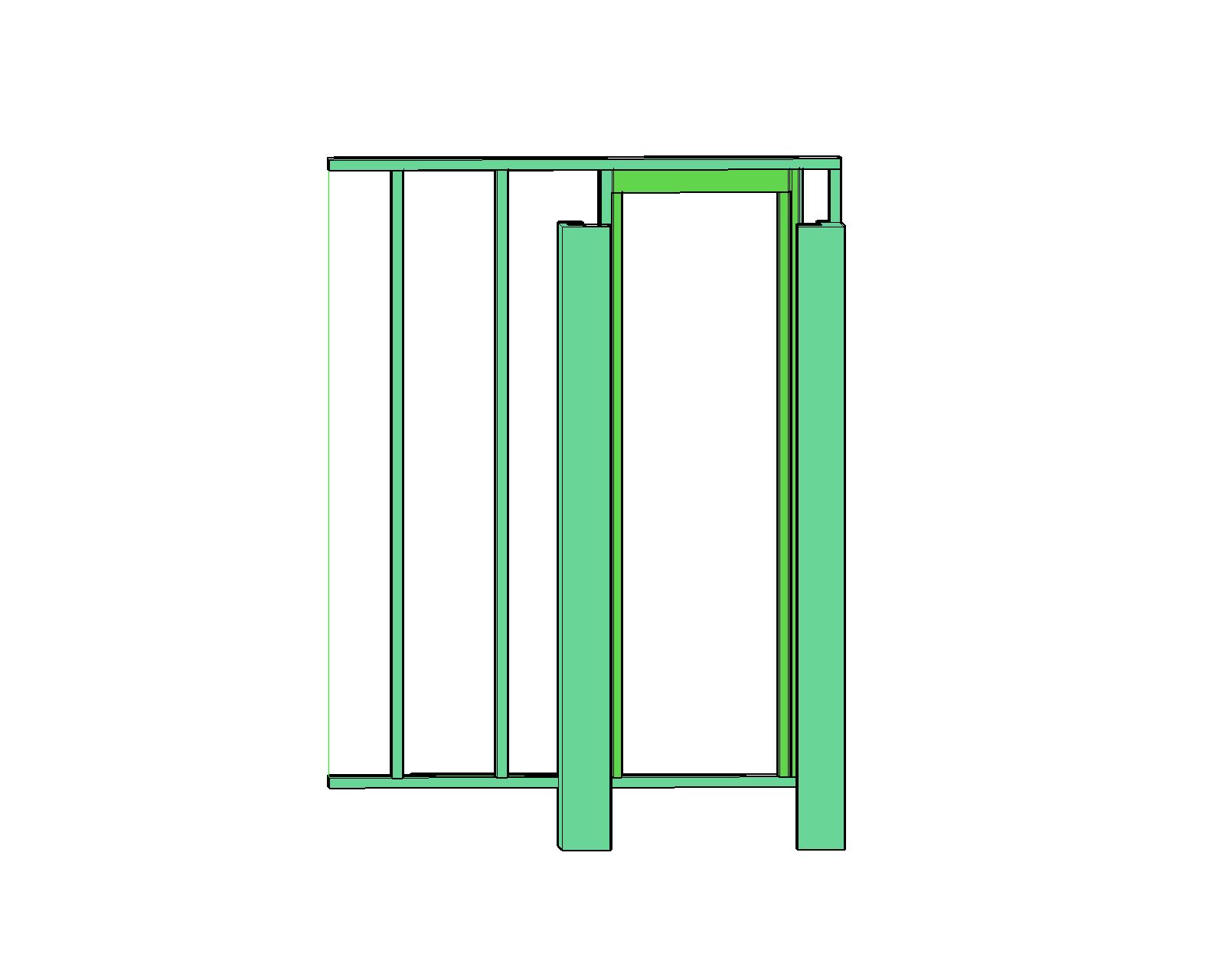
Exterior elevation view of space after existing service equipment is removed and new framing is installed. |
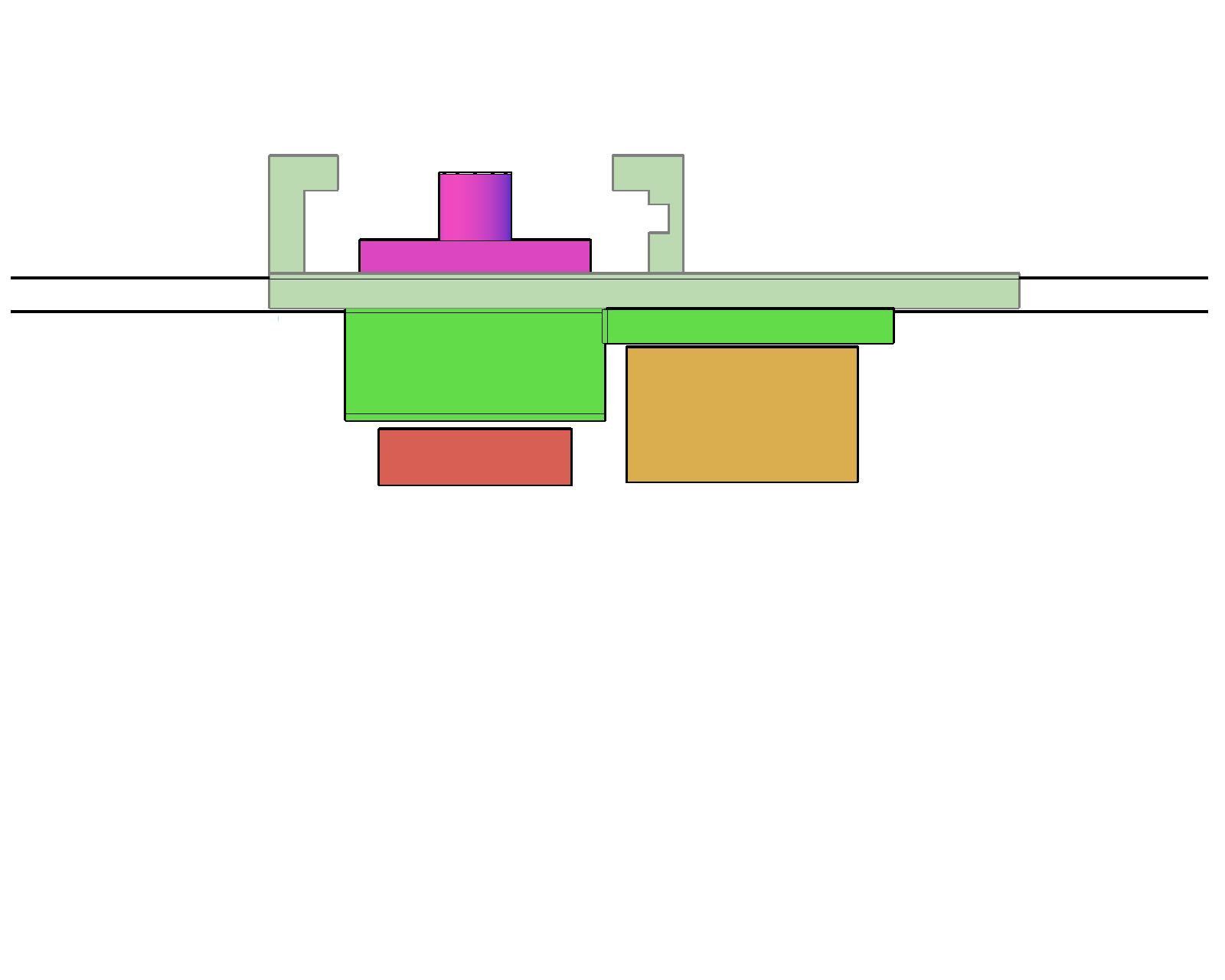
Plan view of area after new equipment is slid into place. |
Installation Progress as of 2/22/21 |
|
 |
 |
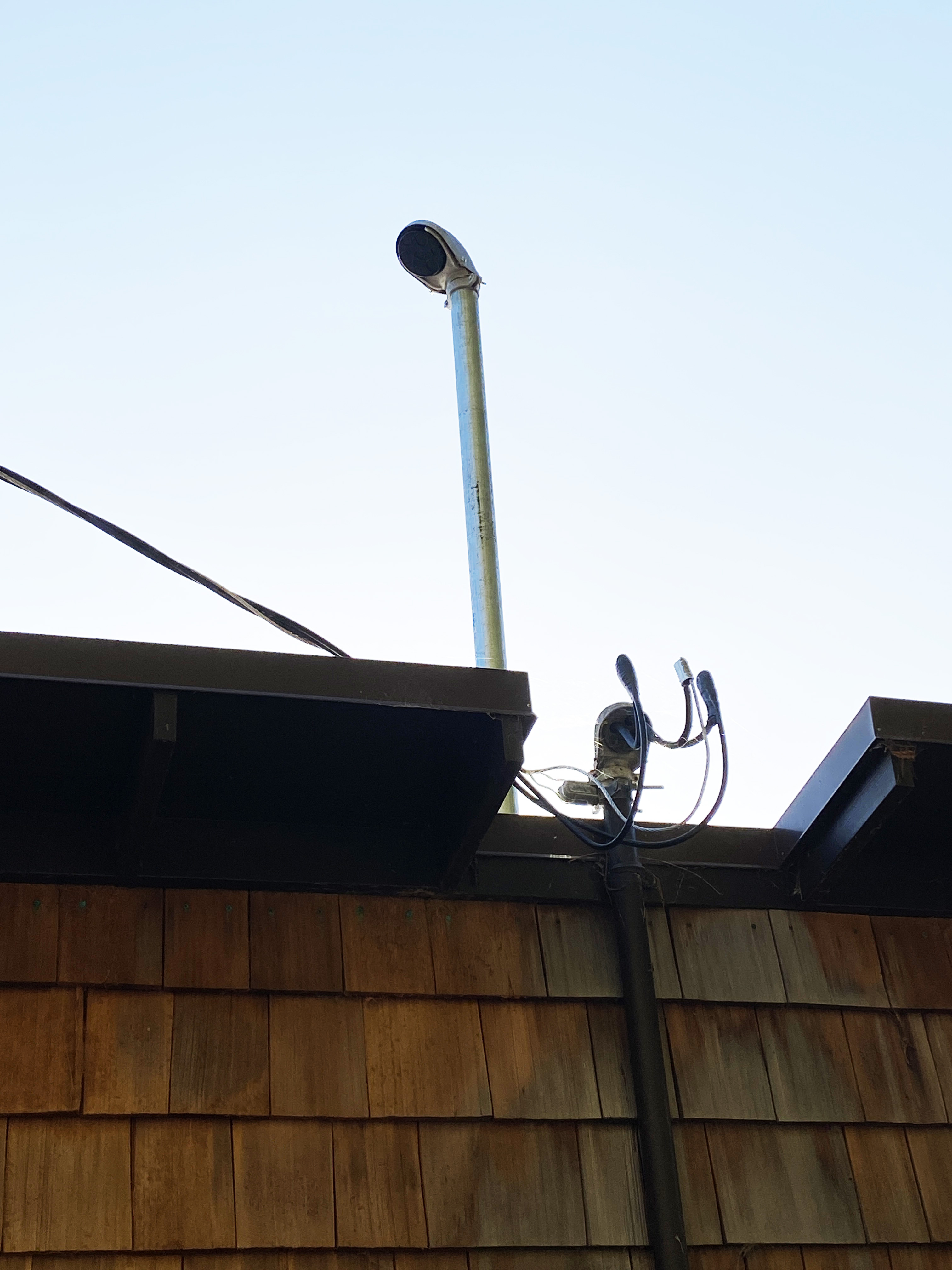
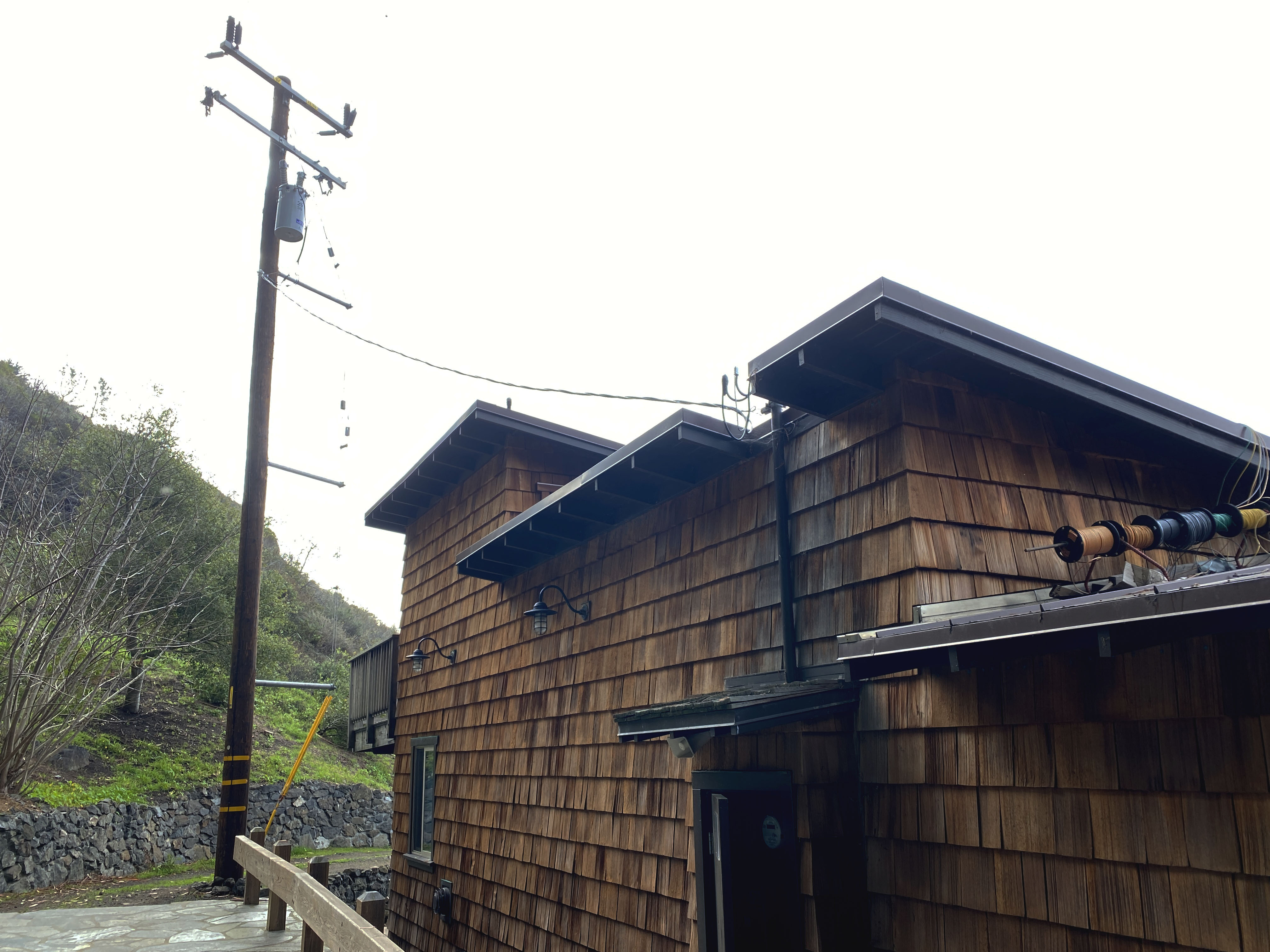
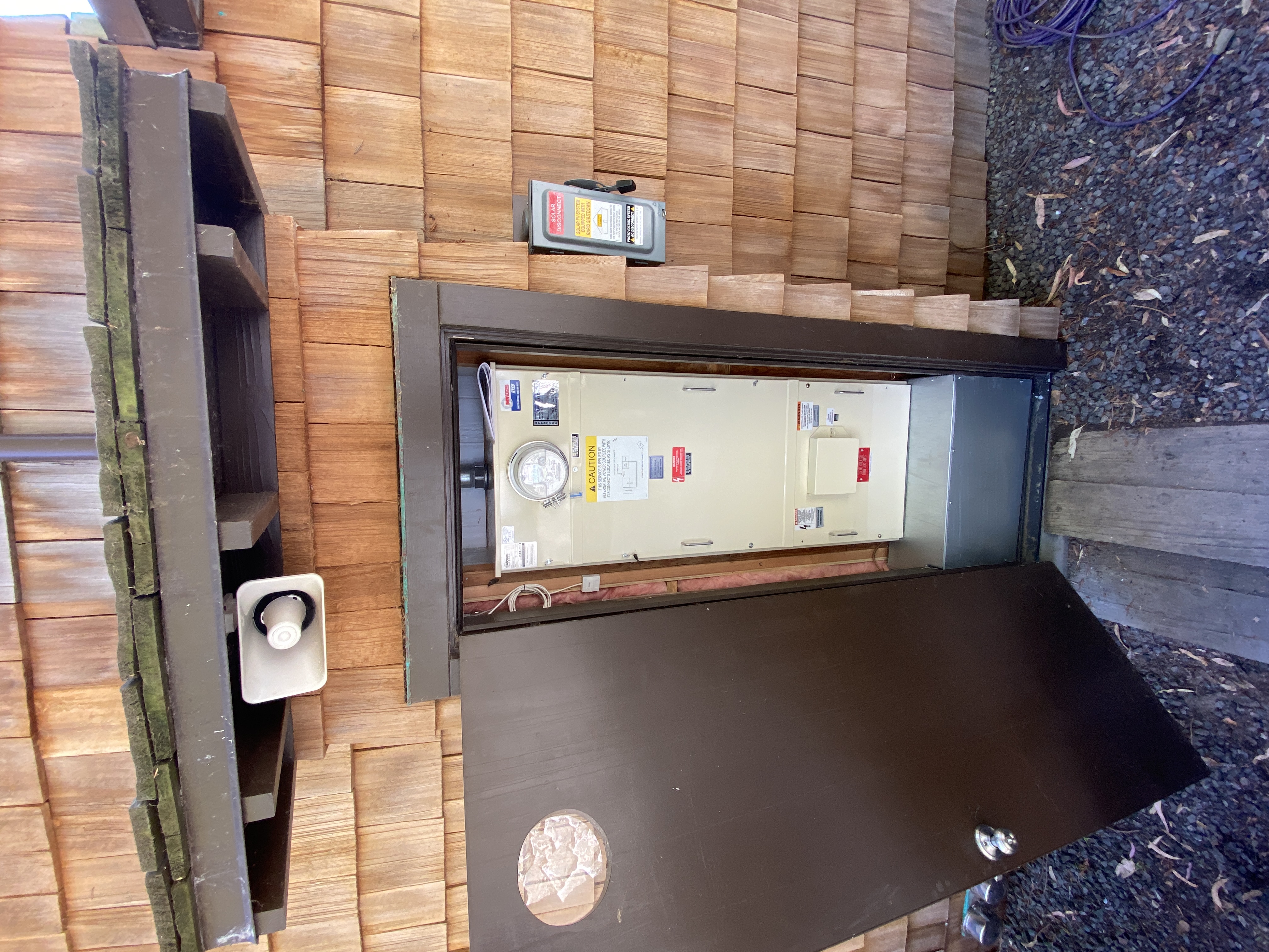
The new mast is installed. It is pushed up higher than final to allow working room underneath. |
The solar disconnect is installed within 10 feet of meter. It is as specified on 1 line diagram. |
 |
|
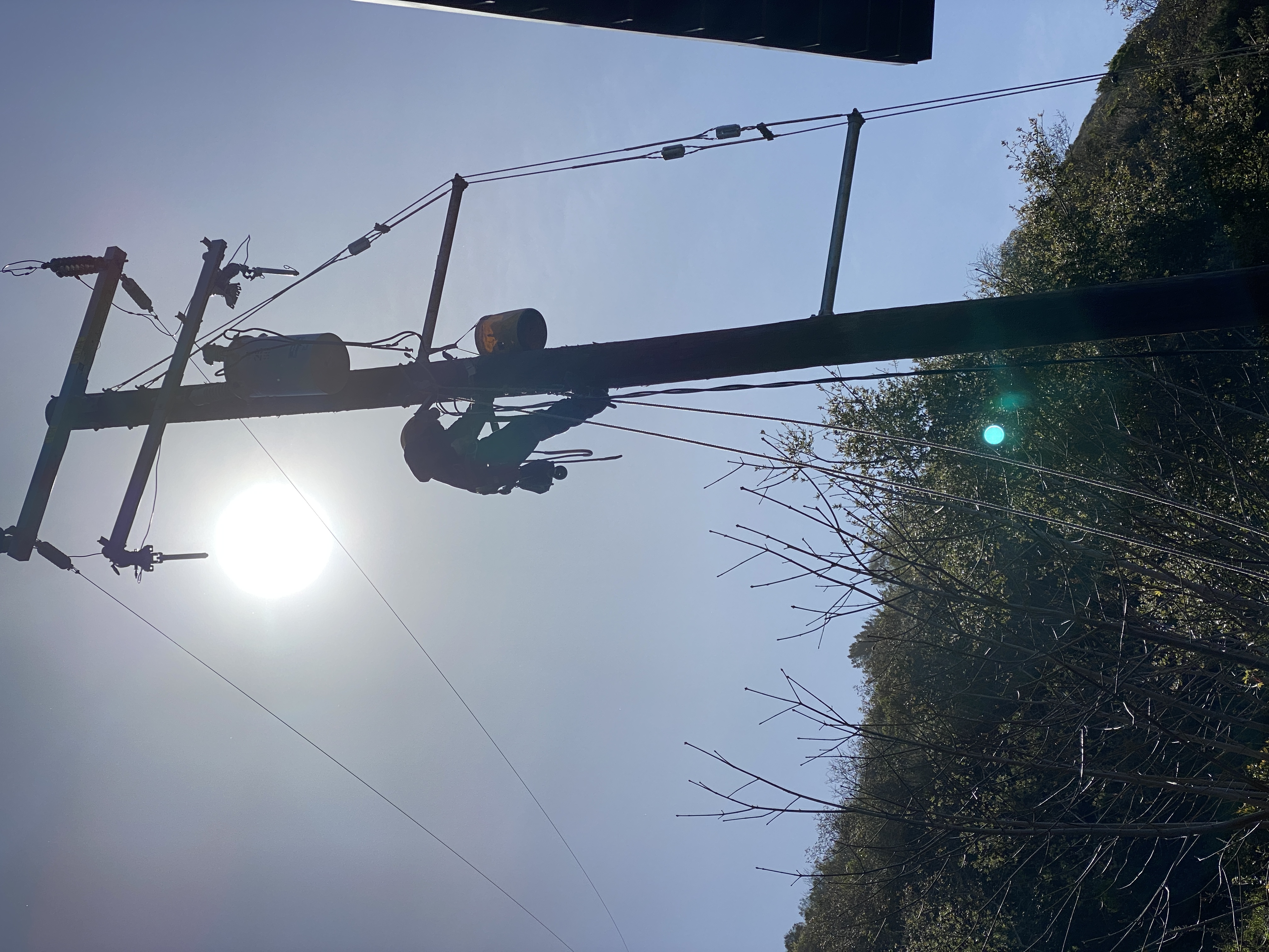
Pole and Drop |
|
The order of operations is: |
|
Documents |
|
Project Complete |
|
 |
 |
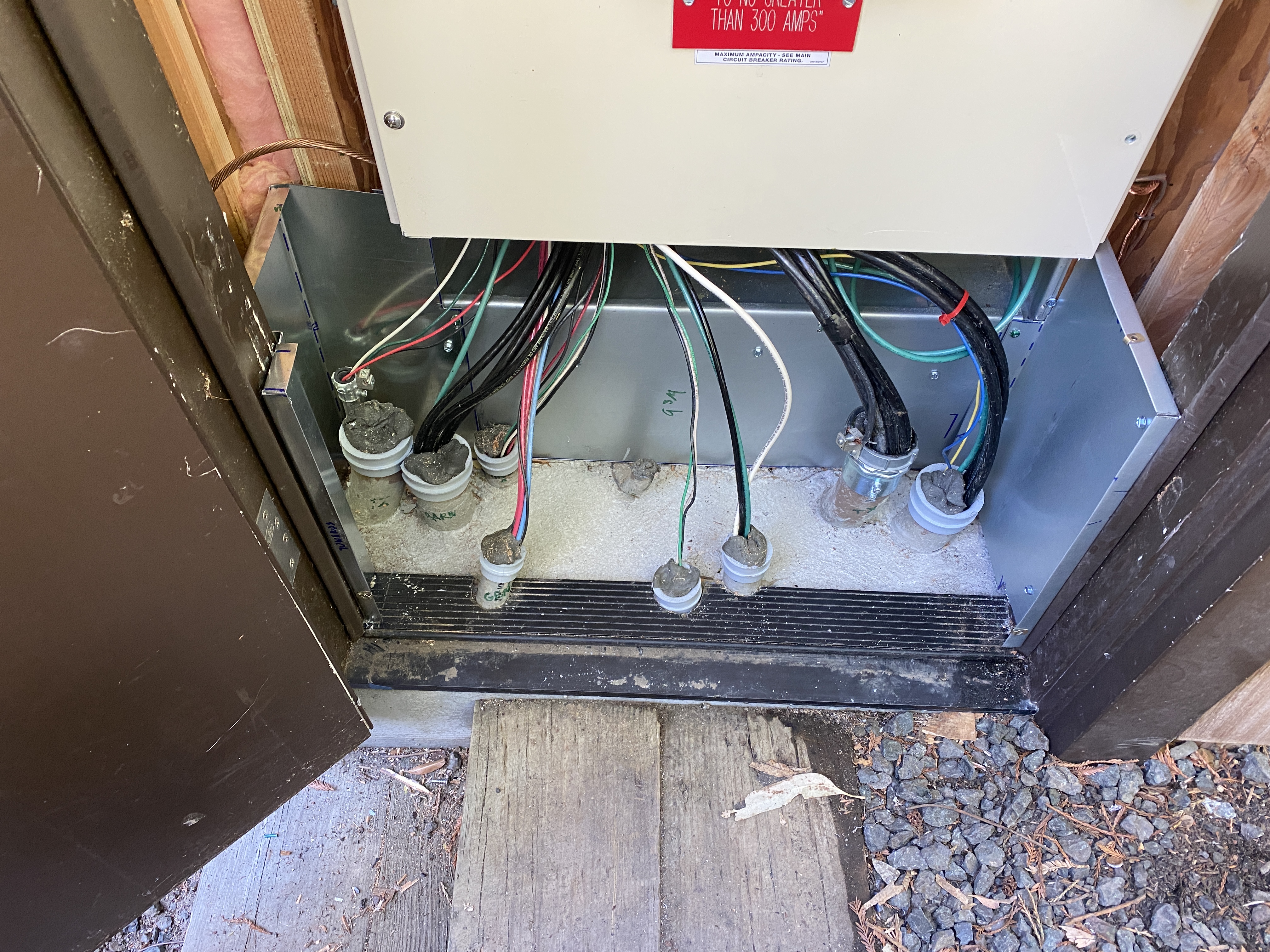
Completed 300A service with custom gutter below to route exterior feeders. AC Disconnect for Supply-side connection to PV system is on the right. |
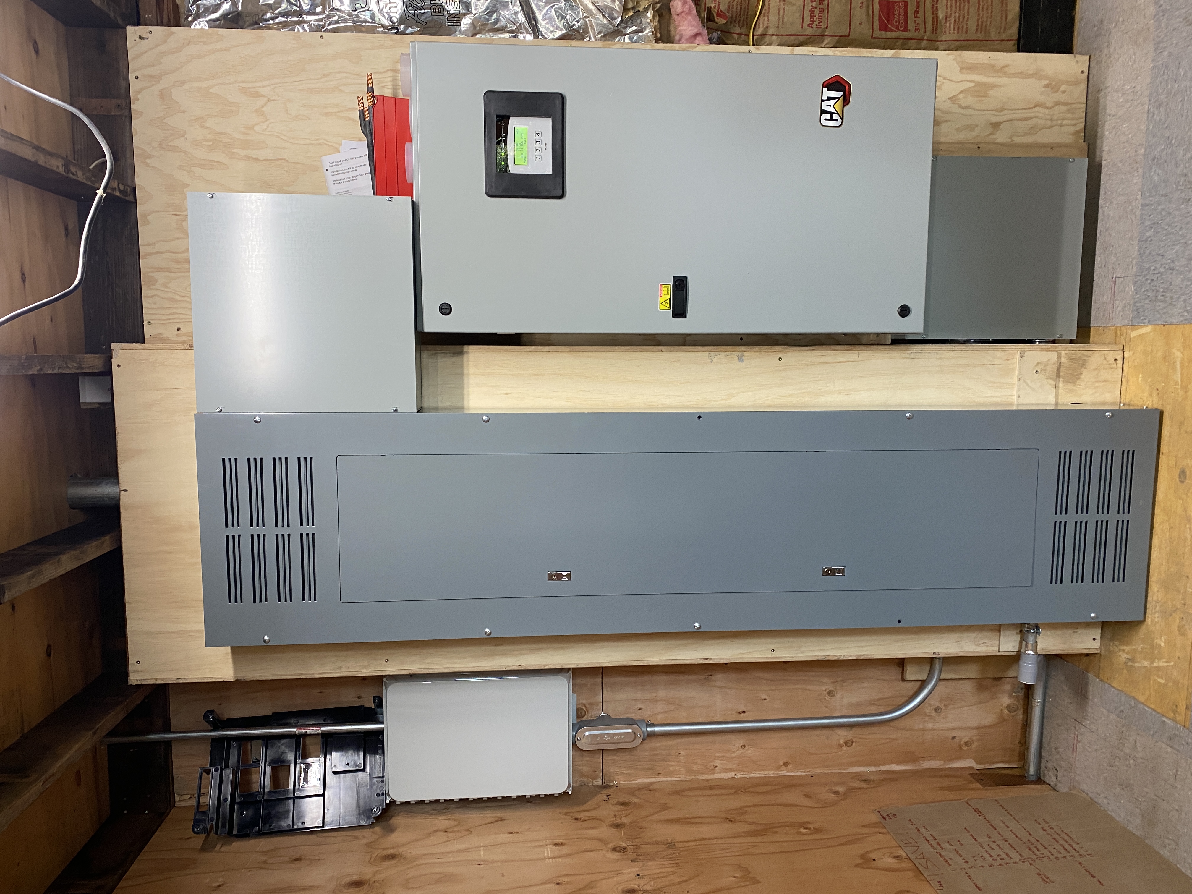
Interior with, from left to right: Enphase Combiner, SquareD load Center and 400A transfer switch. |
|
|
Interior of custom gutter. Leads feed through gutter chase below service to load center or transfer switch. |
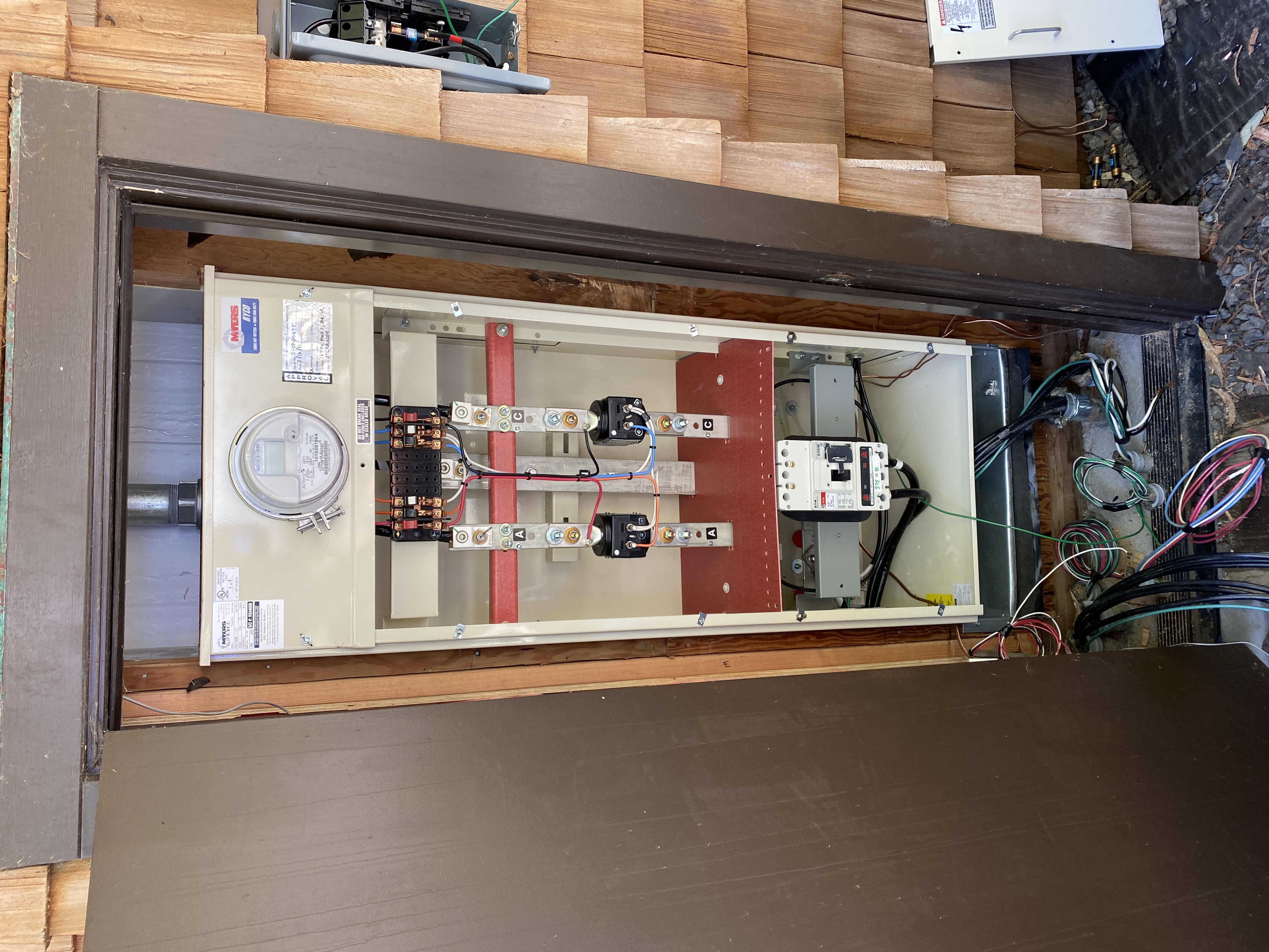
CT section of service after CTs installed and wired. |
 |
Barn Interlock |
| Jack with PG&E connecting the new drop. | Barn Interlock |