CASE STUDY |
|
|---|---|
Problems with the Integration of existing Sunny Island / Sunny Boy AC-Coupled Off-grid System with Fortress E-Vault |
|
| Last Updated: 4/9/25. New information posted at the bottom. | |
Table of Contents Background |
|
| Audience: Technical advisors and non-technical interested observers. Some background information provided to assist the latter. | |
Background: |
|
|
|
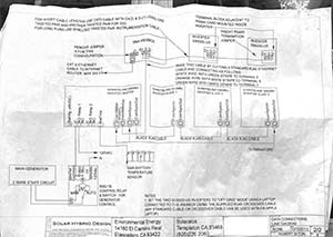
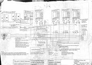
As built line diagrams: (click on any image for full size) |
|
 |
 |
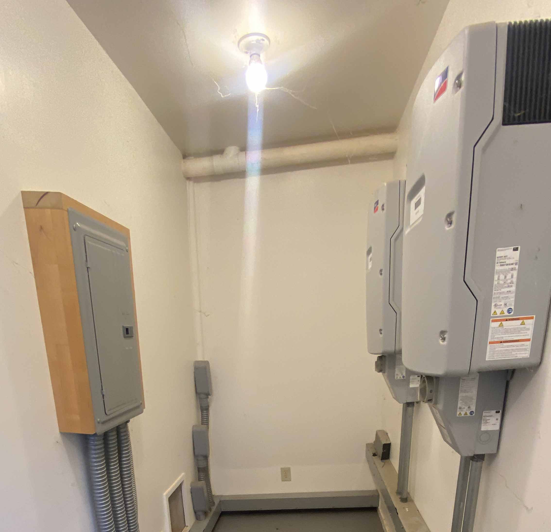
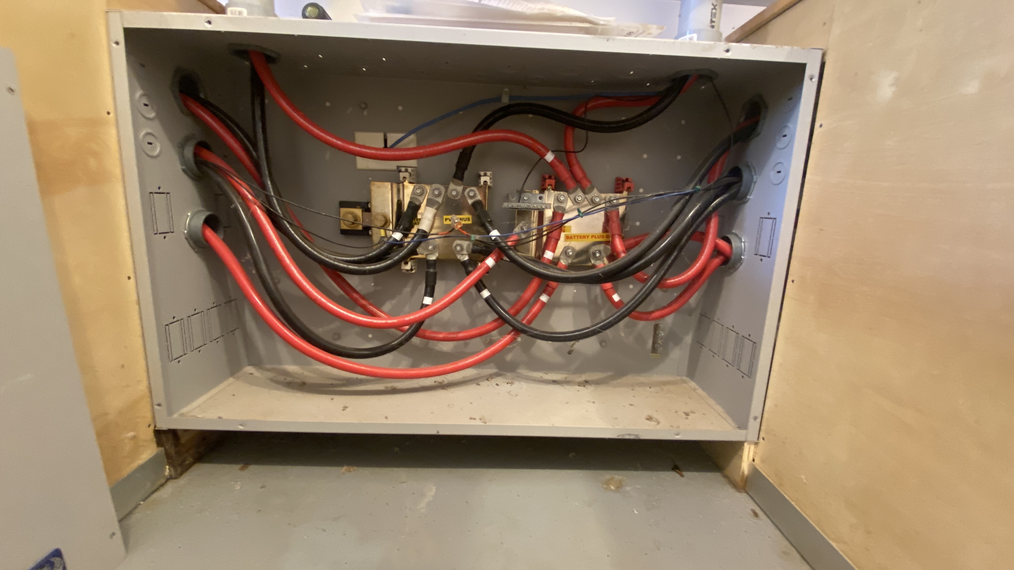
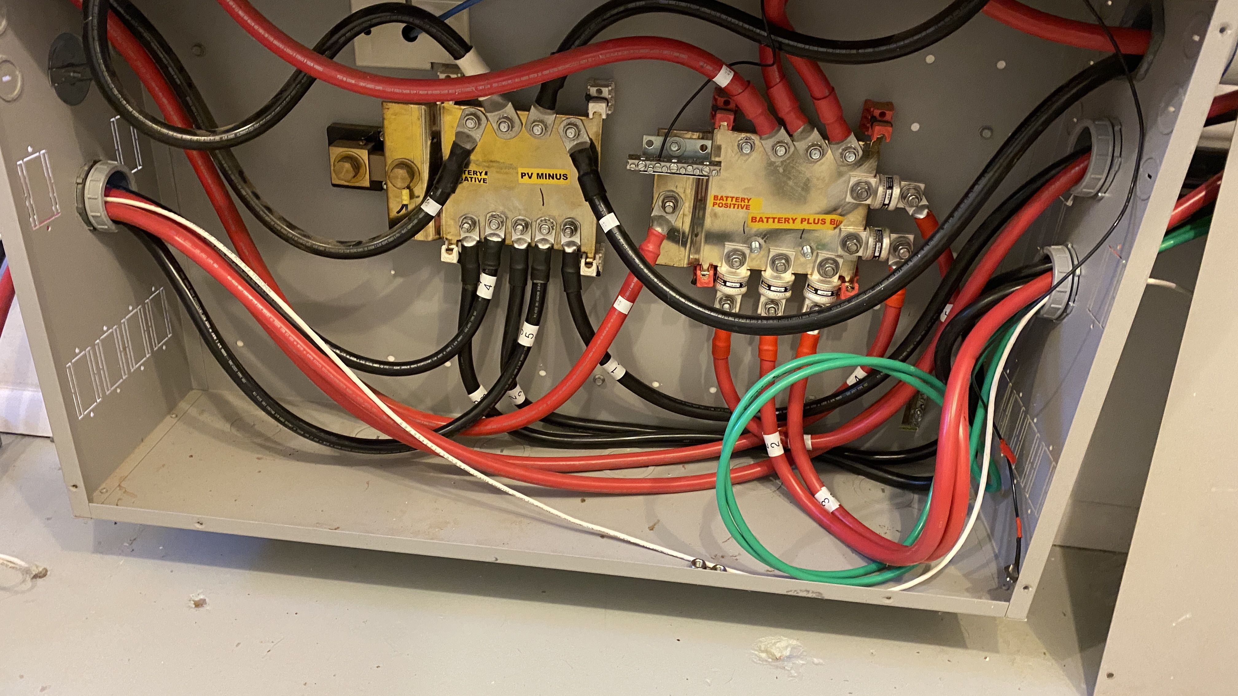
Images |
|
 |
 |
 |
 |
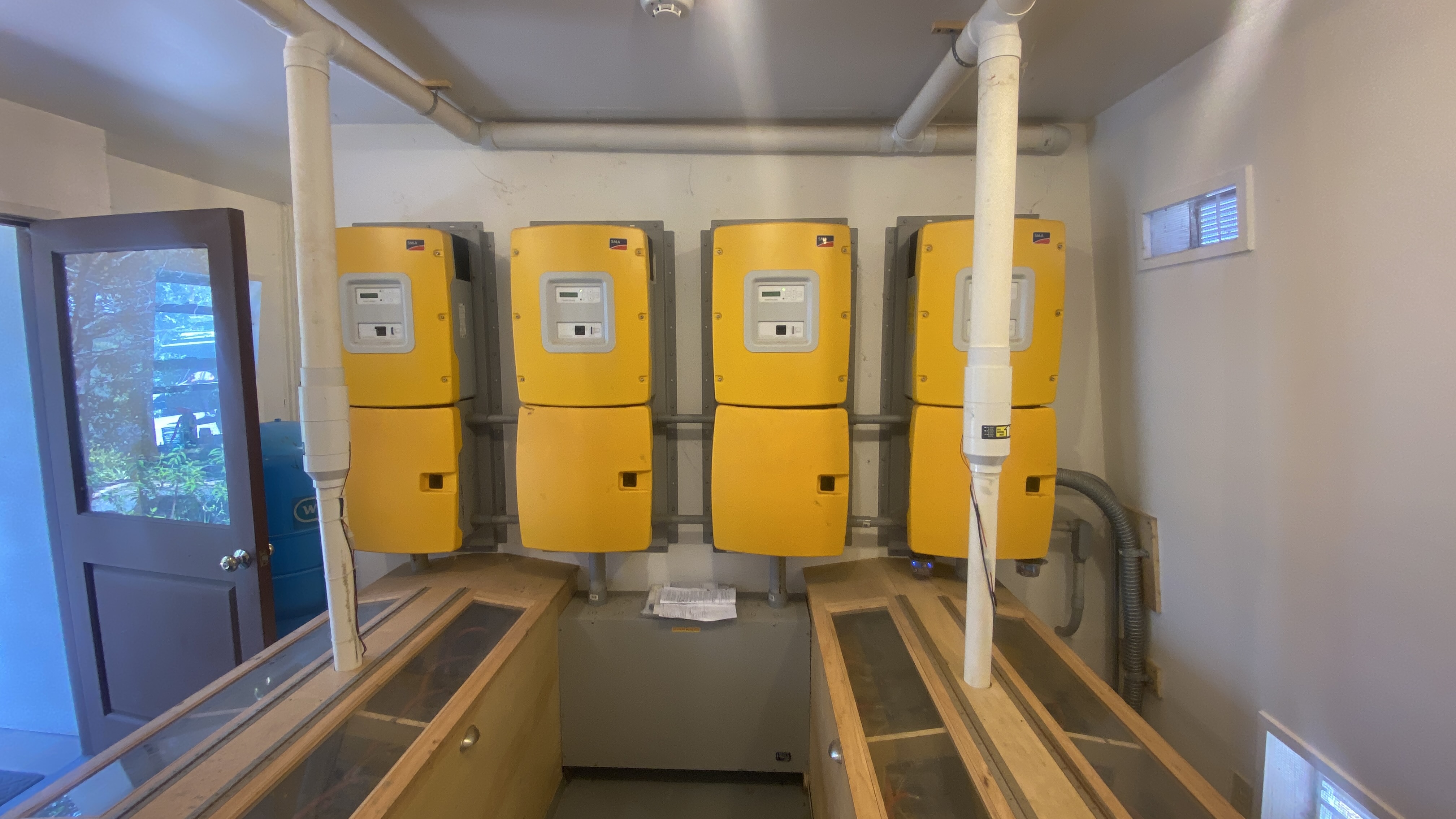
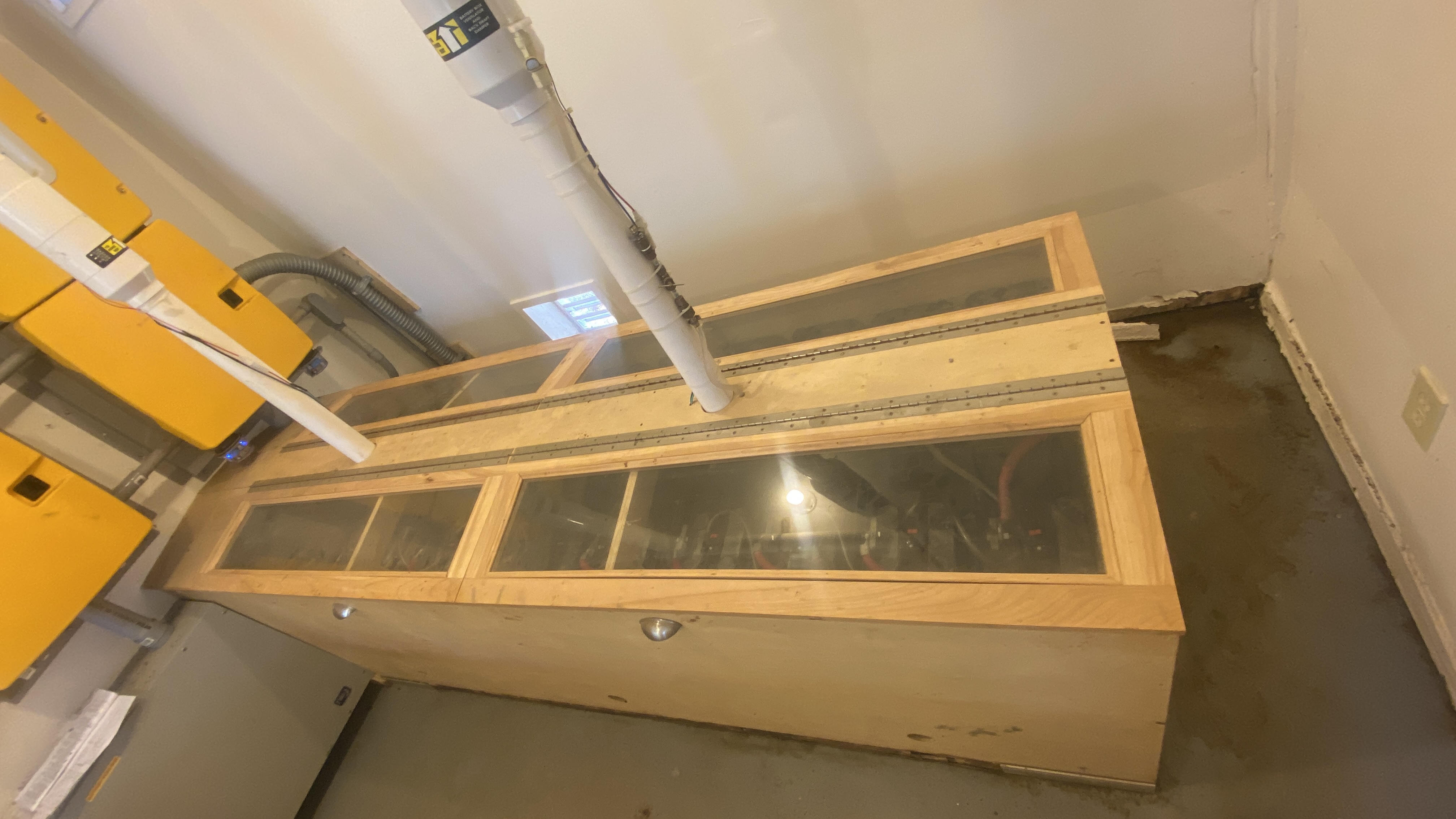
Current project:
|
|
Images |
|
 |
 |
Issues: |
|
1. State of Charge: The Sunny Island inverters perform many functions based on State of Charge. SOC is a calculated value. The process of calculating SOC is used in many applications. See below for a white paper from SMA on battery management. The calculated value is not always accurate. If the value is calculated incorrectly the operations that depend on the value will happen incorrectly. In the few days the system has been operating with the e-Vault battery array I have seen occasions were the two systems have had discrepancies of as much as 50% in their SOC values. I have also seen this difference decrease to 4%. This discrepancy has caused at least one outage. This was because the SI calculated the SOC higher and failed to start the generator in time to prevent the Fortress BMS from disconnecting the battery output. The Fortress e-Vaults have internal Battery Management Systems that calculate the battery SOC, and presumably do that more accurately than would the Sunny Islands. There is a method of connecting the BMS units to the SI master inverter to allow the SI system to use the more accurate BMS SOC values. This is called "closed-loop communications." Several technicians/engineers at Fortress have advised against using closed loop in spite of the obvious advantages, but have not given a plausible reason why not. To use closed loop or not needs to be resolved. (Closed loop was initiated 10/20/23) |
|
2. AC-Coupled charging: This system is set up as an AC-Coupled battery charging system. AC-Coupling is an odd method that is often misunderstood. I could not find any explanation of these two types of systems on the web that described it accurately. See below for an explanation of DC-Coupling versus AC-Coupling. Within a few days of connecting the e-Vault battery bank we started getting battery over-voltage conditions. I measured one event that put the battery voltage at 69 VDC. This happened when the sun was out, the SB inverters were producing and the batteries were at a high level SOC-- greater than 95%. At the time the SI inverters registered about 50% SOC. When the battery voltage spiked the SI inverters went to standby as a predictable reaction to a battery voltage of 69 VDC. At the same time I measured the AC frequency as above 62 Hz. This all happened very quickly and these measurements were recorded on a Fluke 87 DVM in record mode. When the SI system records a battery overvoltage condition the system goes into standby (momentarily shuts off). The system is programmed to restart twice shortly after the shutoff. After that the system goes into sustained standby and requires intervention to restart. At issue is how to prevent this spike in voltage during AC-coupled charging.
|
|
| Resources and background material | |
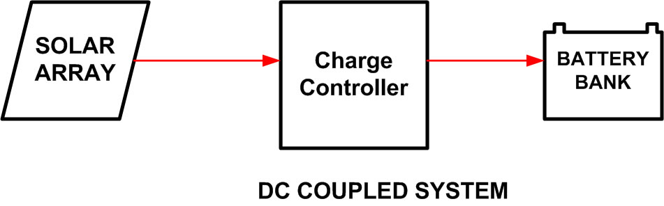
DC Coupling: This is when DC power coming from solar panels remains as DC power. The power is routed to the batteries through a charge controller and the voltage and current is regulated for most efficient and safe battery charging.
|
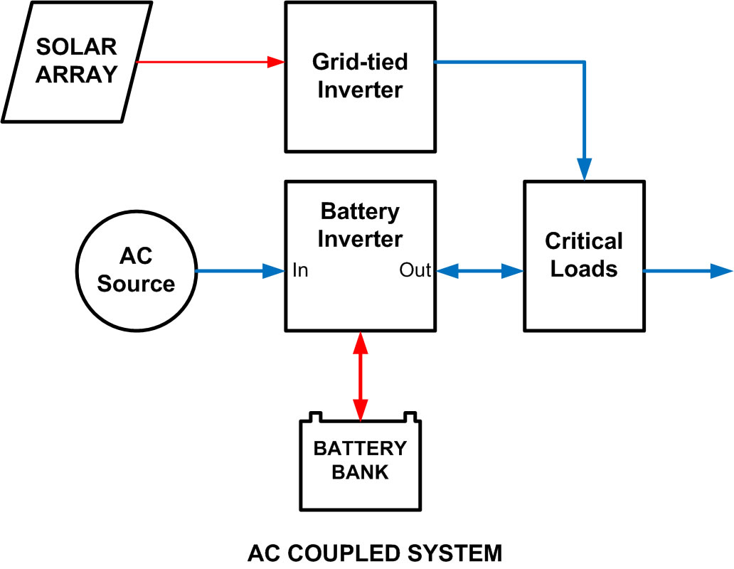
AC Coupling: The DC power from solar panels is connected to a grid-tied type inverter. A grid-tied inverter will not start up unless it sees it is connected to an AC distribution system providing proper voltage and frequency AC power. In an off-grid context this AC power is provided at the OUTPUT of a battery inverter. The PV power travels BACKWARDS through the battery inverter to charge batteries. While travelling backwards there is minimal charge regulation of the power going to the batteries. Some alternate scheme needs to be created to force the grid-tied inverters to shut down or reduce output when the batteries become full. If not batteries could be dangerously overcharged. This is accomplished by either using a relay to disconnect the grid-tied inverter or the battery inverter nudges the frequency up until the grid-tied inverter shuts down or reduces production because the frequency goes out of tolerances. |
DC-Coupled Power Flow
|
AC-Coupled Power Flow |
| SMA AC Coupling v2.3 | SMA Battery Management |
| Fortress Install | Fortress SI Integration v 1.0 |
| Fortress SI Integration v 1.2 | |
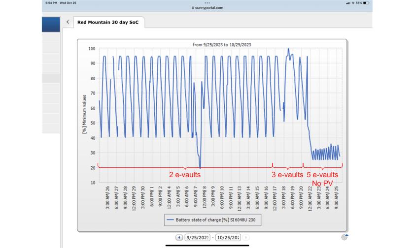
10/28/23:
Note that the overvoltage problem never occurred with only 2 E-vaults installed. |
|
I spoke with a technical support person at Fortress. Fortress apparently has never tested the e-Vault with Sunny Island inverters in an AC-Coupled installation, in spite of what is written here. |
|
| Troubleshooting a problem like this requires formulating a theory and testing it. As of 10/27 this is my current theory: Flooded lead acid batteries maintain relatively low impedance to applied charging voltage. This impedance increases gradually as the battery chemistry changes due to the charging process. This is how AC-coupled charging systems are able to work. Even when FLA batteries approach full charge, the low impedance "clamps" charging voltage at reasonable levels until the battery inverters shut off AC-coupled charging either by opening a relay or shifting frequency. Battery Management Systems protect lithium batteries to prevent overcharge. They do this presumably by increasing the input impedance to charging sources to limit charging current. This increase in impedance prevents the clamping function and allows battery voltage to increase beyond acceptable limits. So why was there no over-voltage problem when running for about 2 weeks with only 2 E-vault cabinets? My theory is that the cabinets remained at a low SOC and the BMS never allowed input impedance to rise. The SI thought the SOC was higher so it raised frequency to curtail charging before the e-Vault impedance increased. |
|
I did some more research now using more appropriate search terms. I discovered this article.
This, my friends, is the exact scenario. It may be that AC coupling is not compatible with lithium battery systems. |
|
| Does Closed Loop inhibit Frequency-Shift Power Control? | |
On October 20 I installed Closed Loop communications between the Fortress BMS units and the Sunny Island inverters. Previously I had found the SOC reported by the Sunny Island differed from that reported by the Fortress E-vault Max batteries by as much as 50%. Once the Closed Loop was initiated the SOC reported by the SI inverters matched the average SOC as seen on the displays for the 5 E-Vault battery cabinets. |
|
After a few days we started experiencing the SI inverters shutting down and displaying battery overvoltage error codes. I experienced this while on-site and recorded momentary battery voltage spikes up to 69 VDC. This was surprising because the Sunny Island is supposed to incorporate a Frequency-Shift Power Control system whereby the Sunny Island systems shifts line frequency upwards when SOC nears 100%. This signals the Sunny Boy inverters to reduce power output, preventing overcharge of the batteries. Remember, battery inverters cannot control battery charging when that charging is the result of receiving AC power into their AC power output ports. I had measured line frequency during the over-voltage events and I did see some momentary increase in line frequency. Why was this not curtailing battery charging enough to prevent the battery voltage spikes? |
|
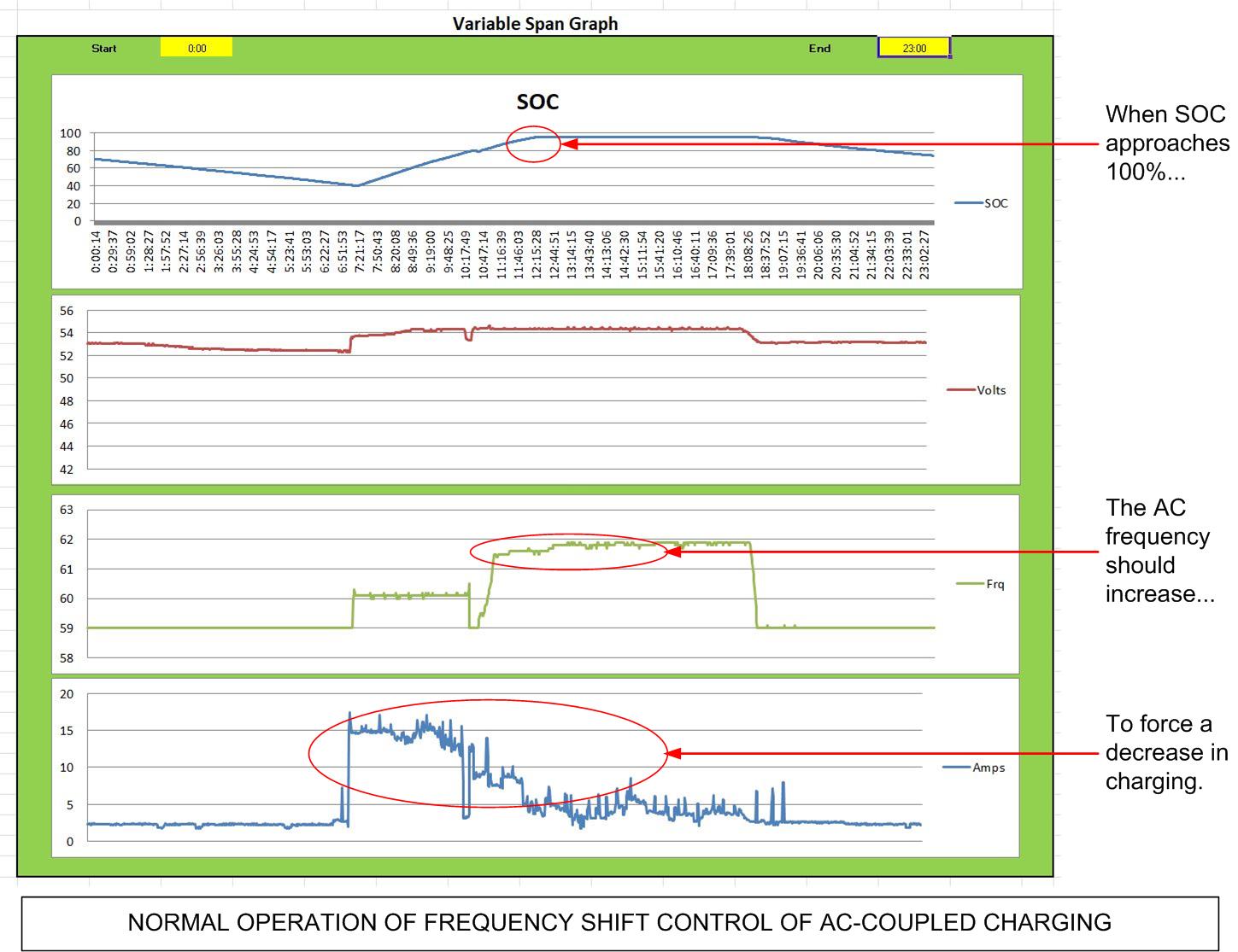
| Fortunately the Sunny Island inverters have excellent data logging. These logs are a bit hard to interpret but I built a spreadsheet tool to help with that interpretation. Below are some graphs created from those log files. | |
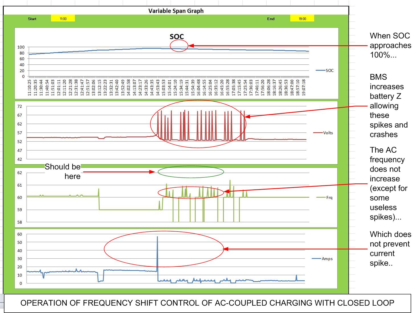
Graph of selected parameters during AC-Coupled charging with Open loop communications. Note that the Frequency-Shift Power Control is working as advertised. (Click image to enlarge.) |
Graph of selected parameters during AC-Coupled charging with Closed loop communications. Note that the Frequency-Shift Power Control is NOT working as advertised. (Click image to enlarge.) |
| The take-away from these graphs is that the line frequency delta for closed loop is much less than for open loop systems and is apparently ineffective in controlling over voltage. | |
If anyone wants to look at the underlying data, here are the spreadsheets: |
|
Concluding question: When programming a Sunny Island inverter for Closed loop, does it have the unintended consequence of disabling Frequency-Shift Power Control? If so, using the Sunny Island in AC-Coupling with Fortress e-vault batteries, and possibly any battery with a Battery Management System, is not viable, contrary to the claim made on this website. (February, 2025: We found that the Frequency Shift Power Control system started working consistently with closed-loop communications. We are not sure what changed but FSPC is now working. This does not prevent overvoltage faults but the frequency shift occurs and power production curtails.) |
|
|
In order to prevent outages due to overvoltage, we installed a system to inhibit the PV charge based on SOC. We used Relay 2 in the Sunny Island Master programmed for Load Shed. When that relay closes a set of contactors opens and disconnects the AC Connection to the Sunny Boy inverters. When the SOC drops below a programmed level Relay 2 opens up and the contactors close, reconnecting the Sunny Boys. Unfortunately the Sunny Island has some limits on the setting values available: The highest value we can set for Relay 2 to close is 90% SOC. The highest value we can set for the relay to open is 80%. This results in very inefficient charging: The batteries never get to 100% SOC. After the batteries got to 90% it may be some hours before the SOC falls below 80% and enables charging again.
|
|
|
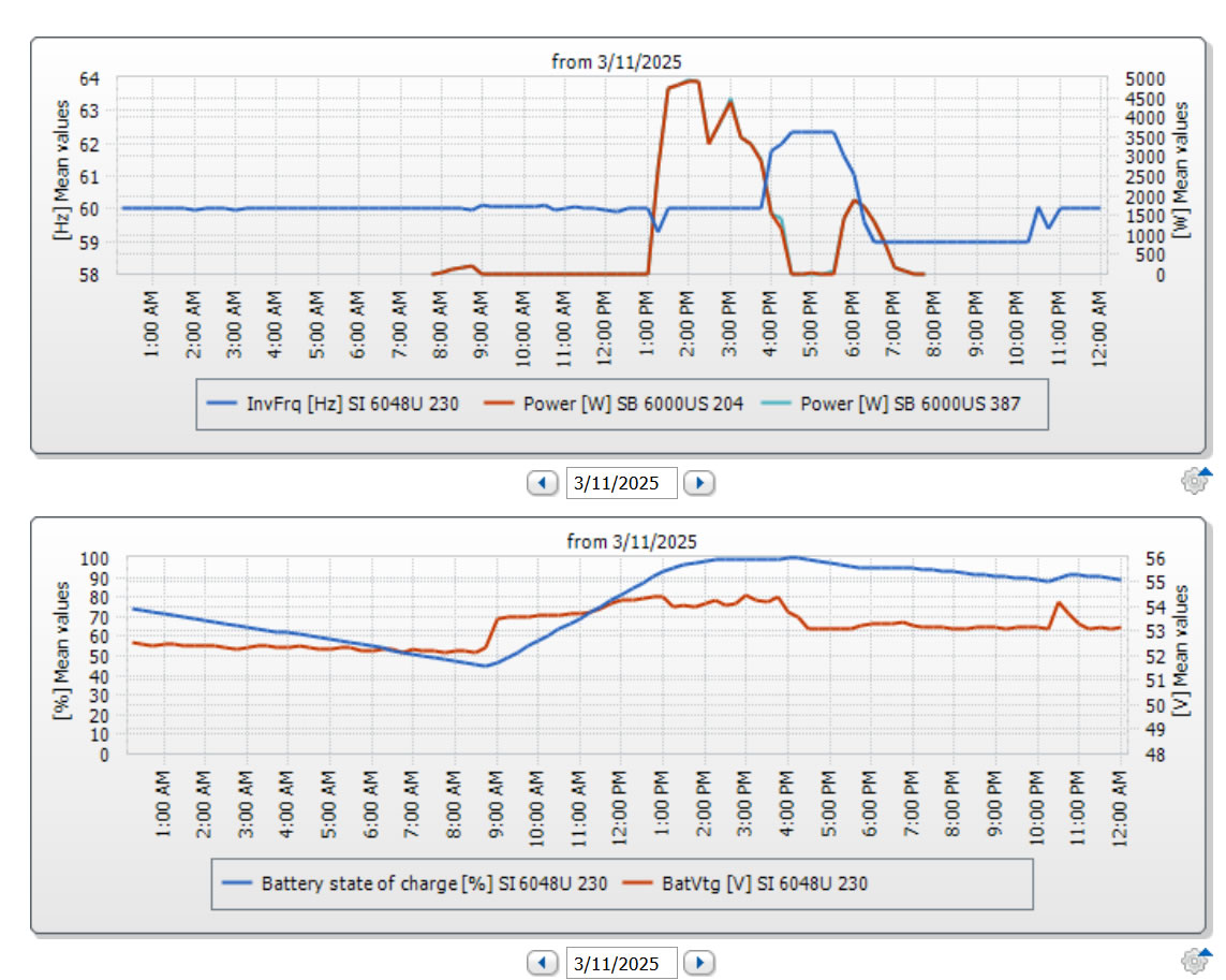
Fortress updated the BMS firmware to try and prevent the problems we are experiencing. We ported in this new firmware on this date. We had to wait for a couple of weeks before clear weather returned so that we could observe the system with full PV capabilities. On the first clear day we received an overvoltage shutdown. The Sunny Island will shutdown and then automatically restart twice before shutting down awaiting a human reset. What was unique after we applied the new firmware is that the Sunny Island system shut down once, restarted and stayed on. Below are two graphs depicting the Inverter Frequency versus PV Charge and State of Charge versus Battery Voltage.
|
|
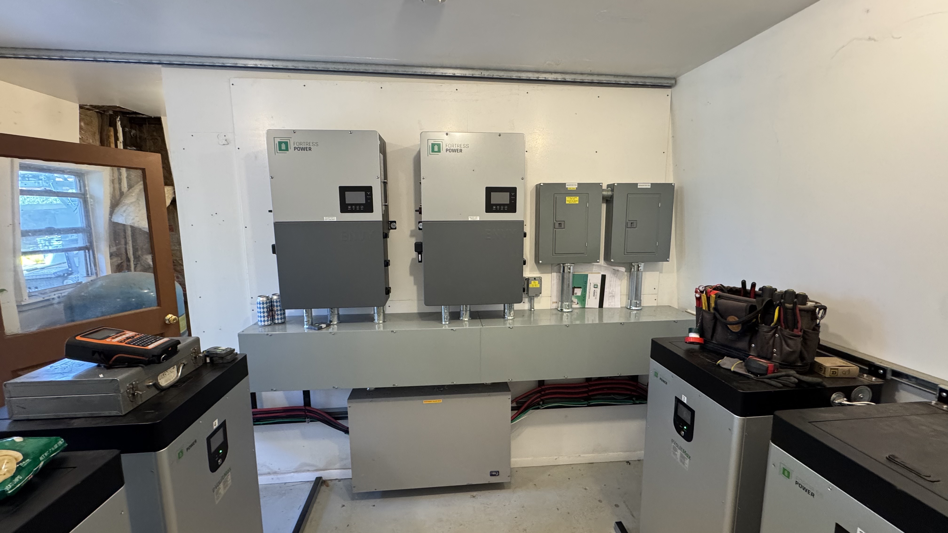
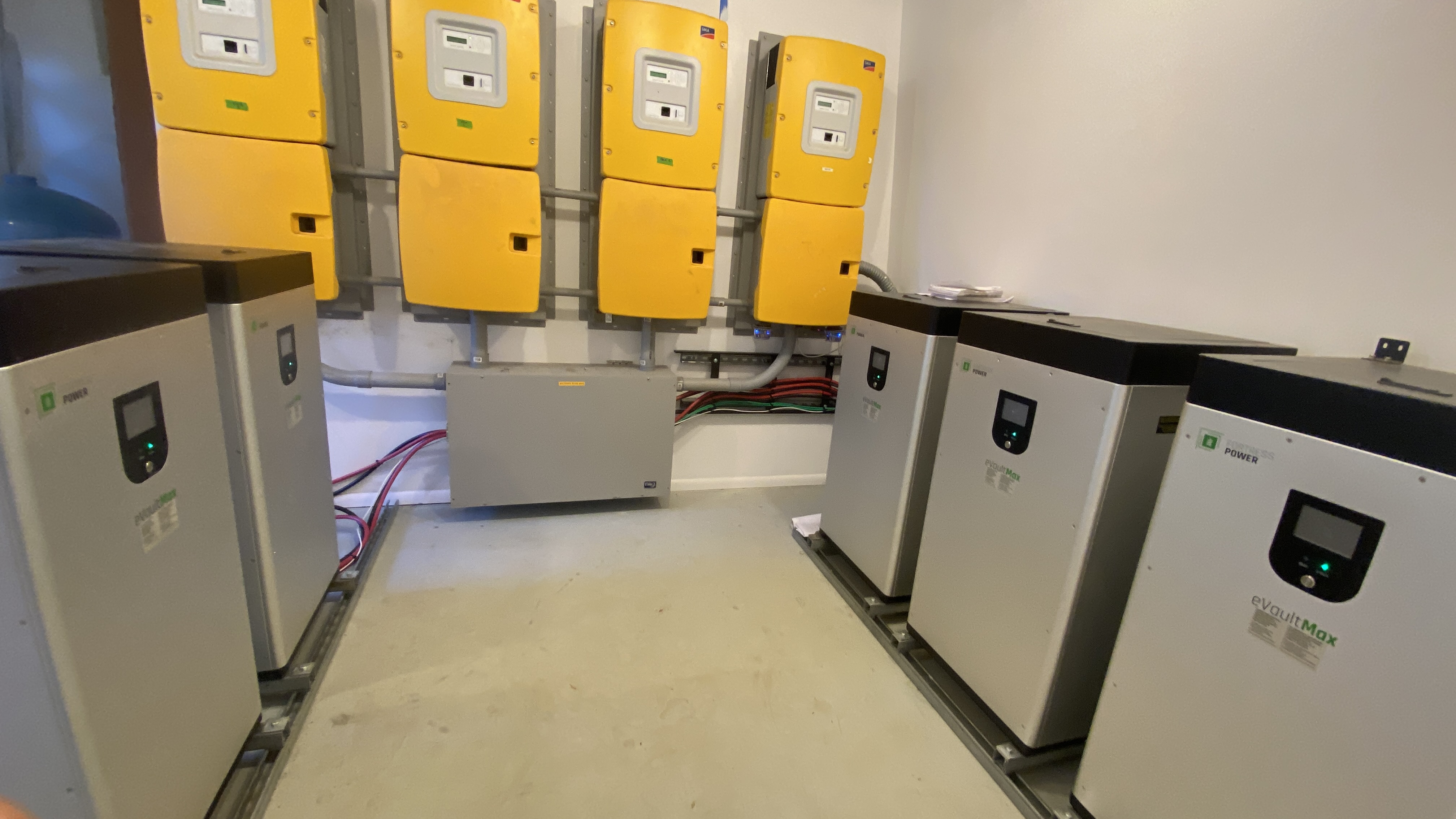
Update 10/1/2025 We gave up on the Sunny Island Inverters and installed 2 envy 12 inverters. So far they seem to be running well. There are a few features missing but Fortress is back-filling these features in a reasonable time frame. |
|
New Envy 12 Inverters with Evault max batteries |
|
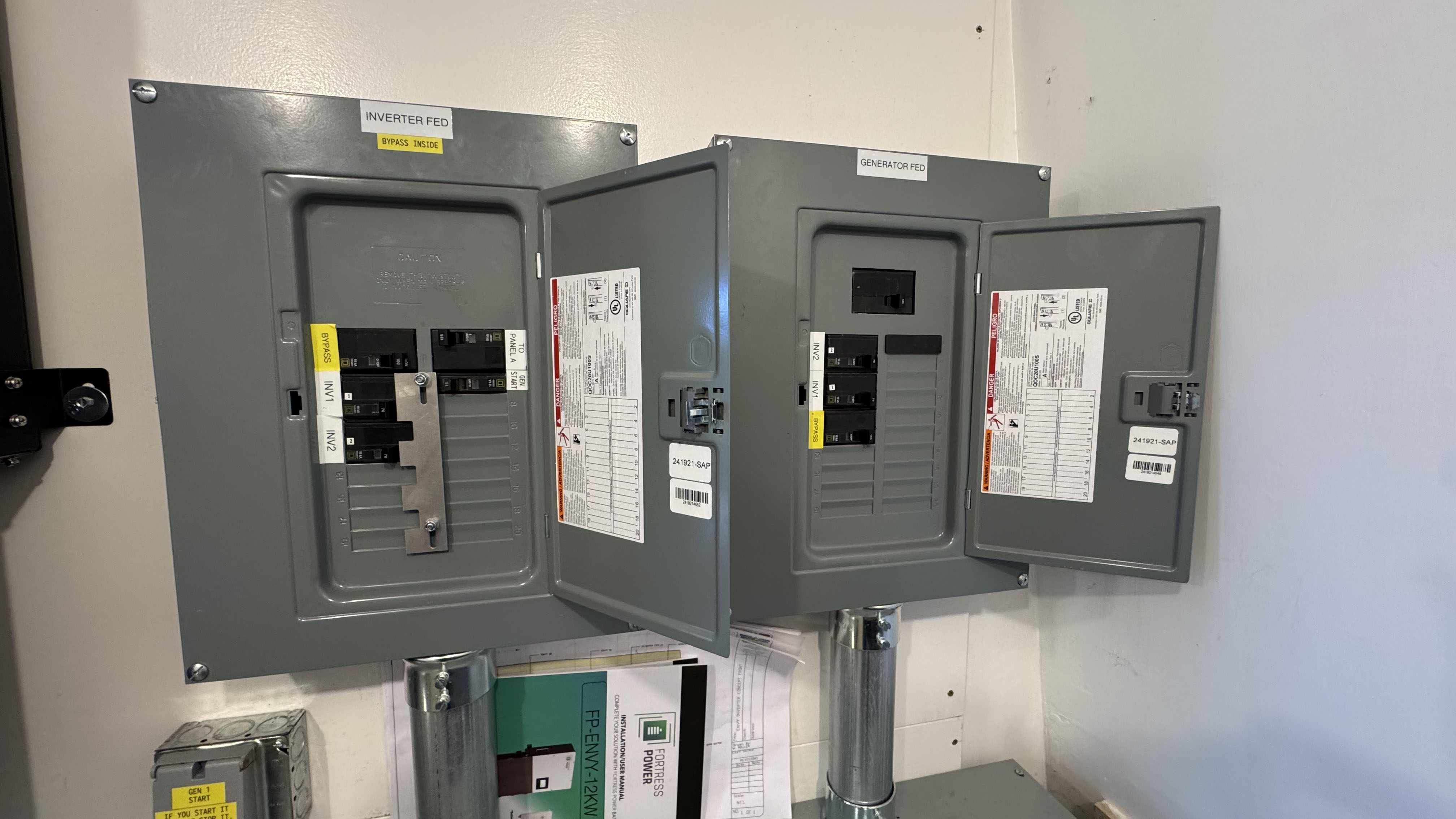
AC Breaker Panels |
|