BYPASS / TRANSFER SYSTEMS |
|
|---|---|
| Click on thumb-nail for full size | |
| Below is a deep dive into the subject of off-grid power system reliability. I apologize for the length of this article but the subject has a lot of nuances that need to be addressed. At the end of this discussion I will display the interlock I have developed that I think is a universal solution. | |
Redundancy is a key part of reliability. In power systems, having more than one power source helps prevent power outages. The most basic form of backup power might be a generator that can provide power if the grid fails. In this case, there has to be a means to switch the feed to the loads (lights and appliances) from the utility supply over to the generator. It is imperative that the generator not feed the utility and the utility not feed the generator. This is usually done by means of a mechanical, double-throw switch that makes it impossible for the two power sources to be connected to each other. The device has pivoting "wipers" that can be rotated to connect the output to either the utility input or the generator input-- but never both at the same time. This device is called a transfer switch. These can operate manually or automatically. |
|
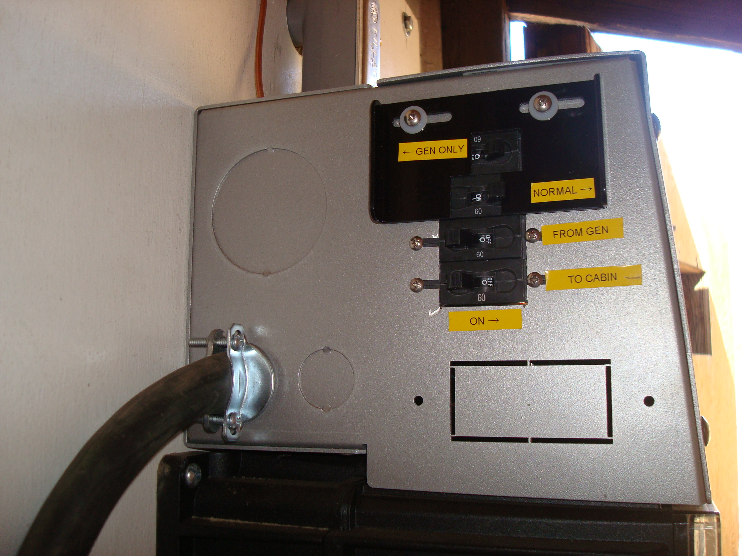
| Manual transfer switches have a handle that is activated by hand and moves the wipers from connecting to one source or to the other. Below are pictures of manual transfer switches: | |
Two pole transfer switch. The neutral is not switched in this case. |
Three pole transfer switch with auxiliary contacts. The aux contacts open and close as the handle is moved and allow a generator start signal to be directed to the generator currently connected. |
| Below are automatic transfer switches. These have wipers that move automatically by electromagnetic force. | |
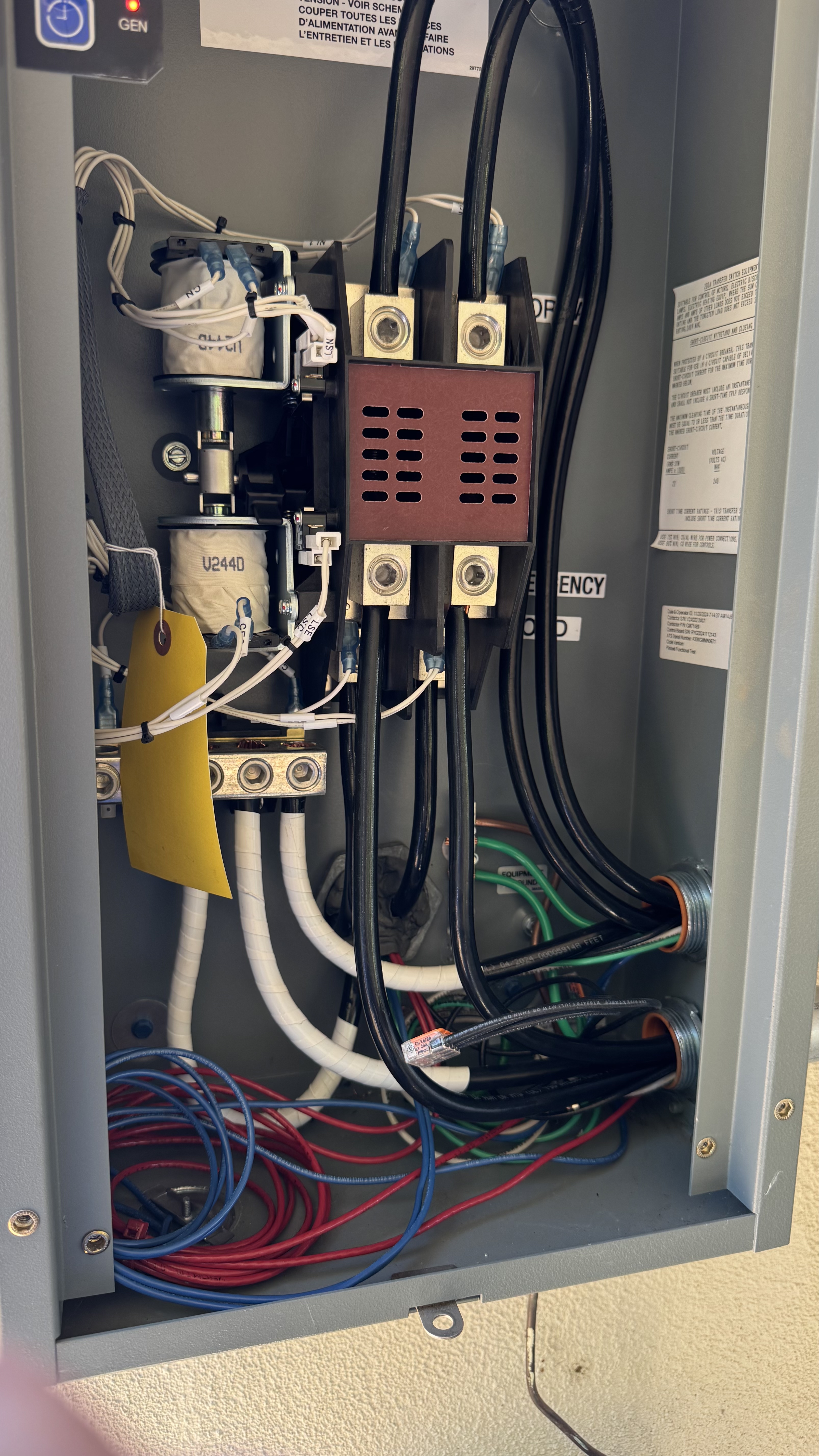
Kohler RXT100. This switch accepts utility on the Normal contacts and Generator on the Emergency contacts. The switch senses loss of utility, starts the generator and transfers to the emergency contacts. |
Kohler RDT. This switch will transfer to whichever input has power. |
| Circuit Breaker Panel Interlocks | |
| The transfer function can also be accomplished by use of circuit breakers that are outfitted with a mechanical means to allow one breaker to be turned on (backup power source) only if another breaker is turned off (main power source). This device is called an interlock. | |
| Factory Circuit Breaker Panel Interlocks | |
| Interlocks are provided by circuit breaker manufacturers to be installed in their breaker panels. They allow only two breakers to be interlocked. This limits the installers options. Below are photographs of interlocks installed in breaker panels manufactured by a few different companies. | |
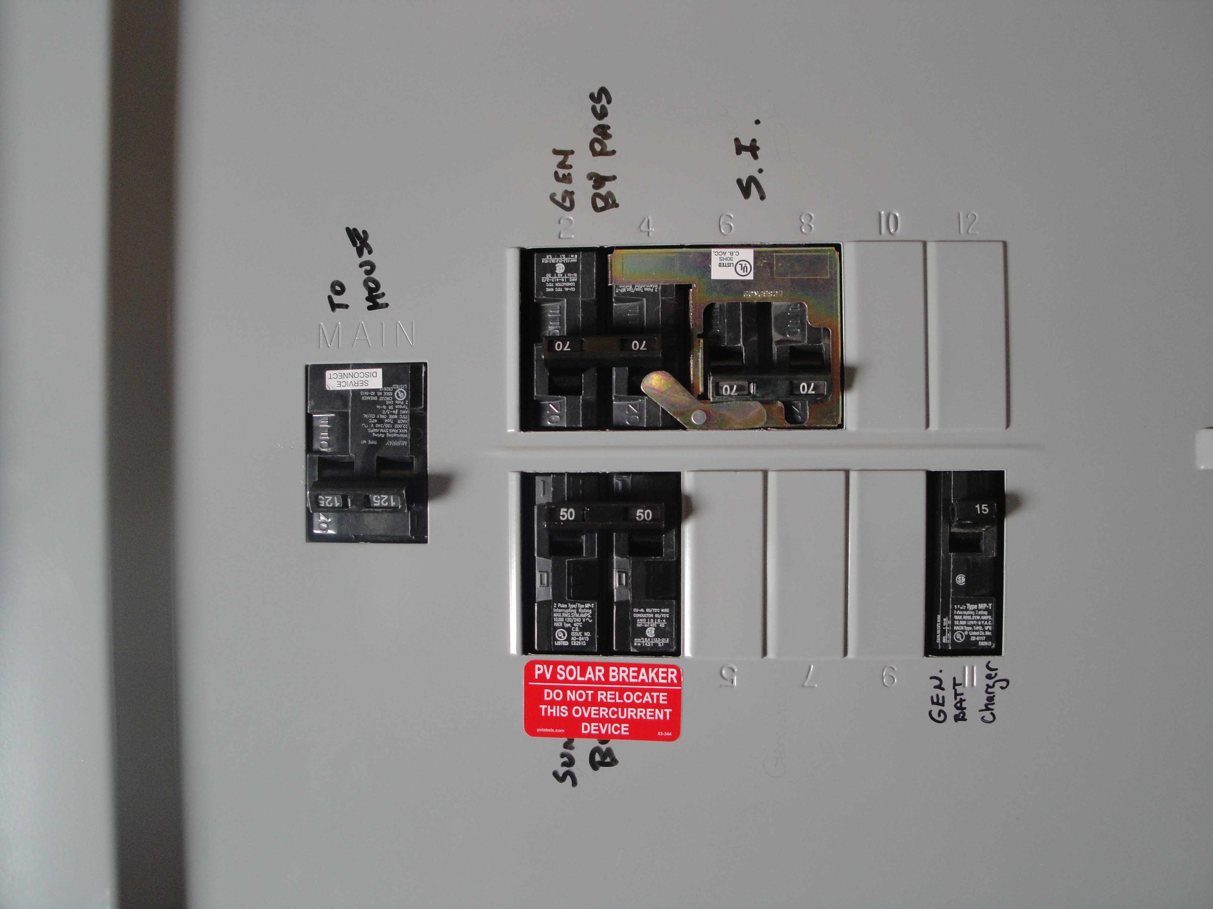
I think this is a Murray panel. This is a form of what I call a Rams Horn. |
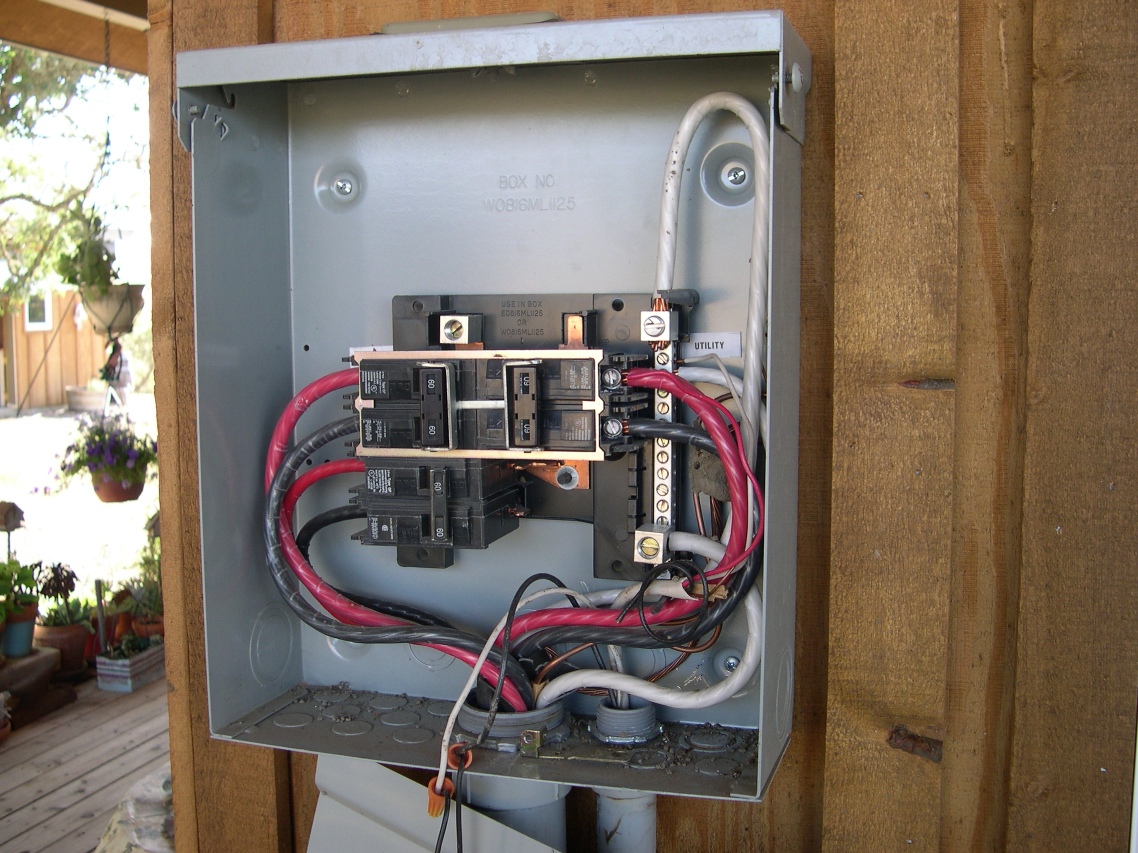
Not sure what brand this is but there is a horizontal bar that makes it necessary to turn one breaker off before the other one can be turned on. |
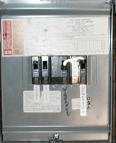
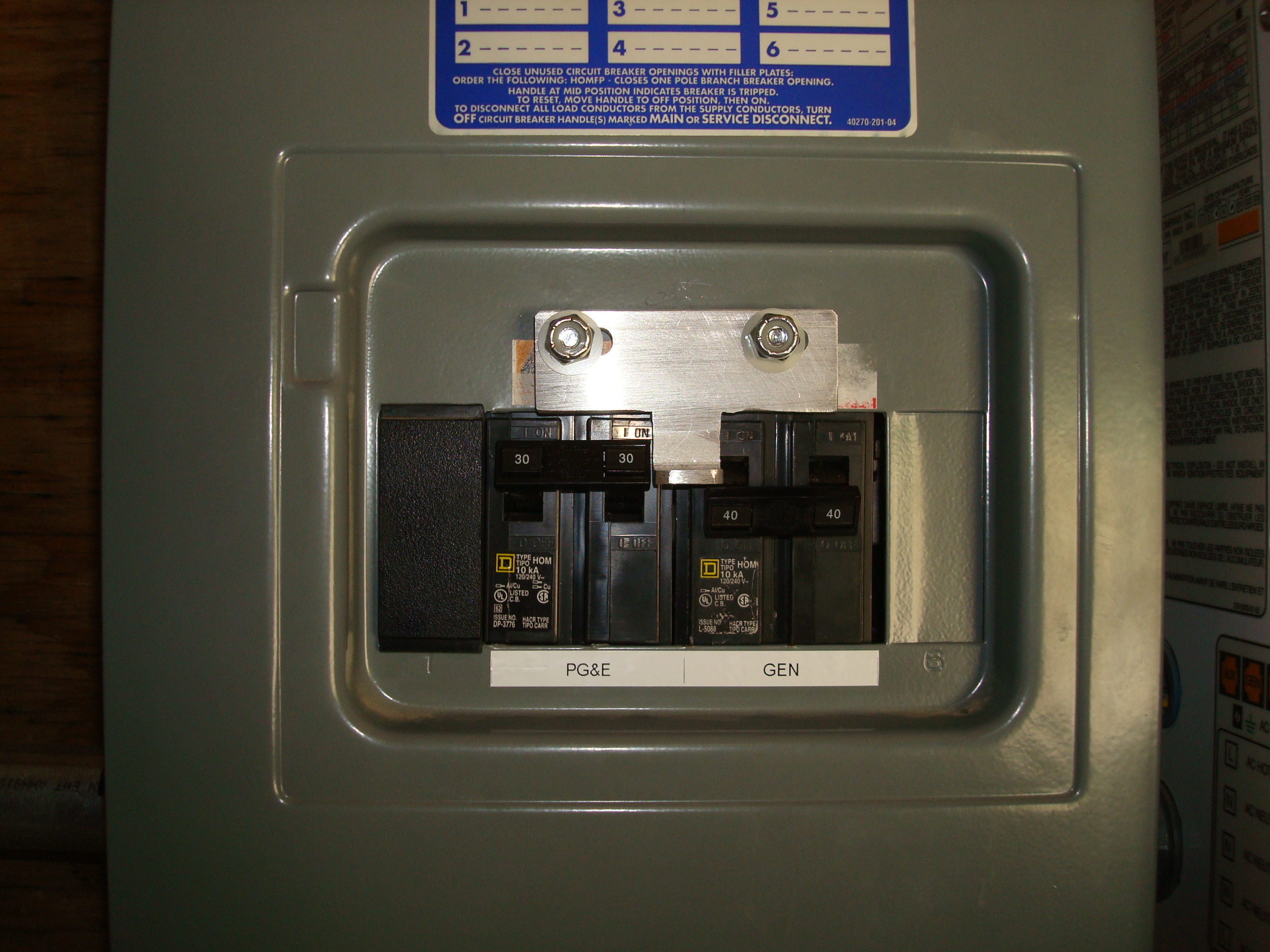
I think this is a Square D Homeline panel. This is a 120 volt only system with a 1 pole breaker interlocked with another 1 pole breaker. |
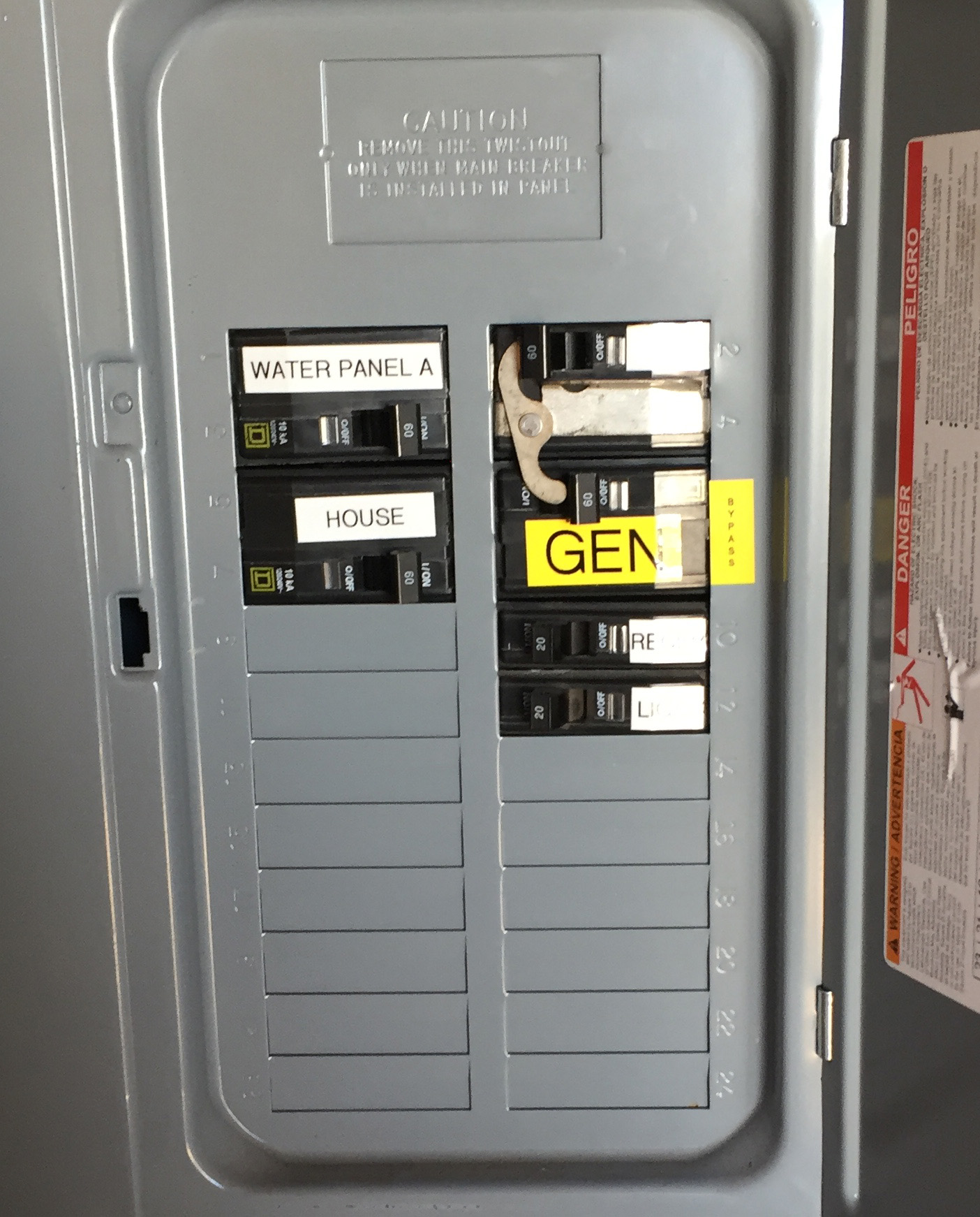
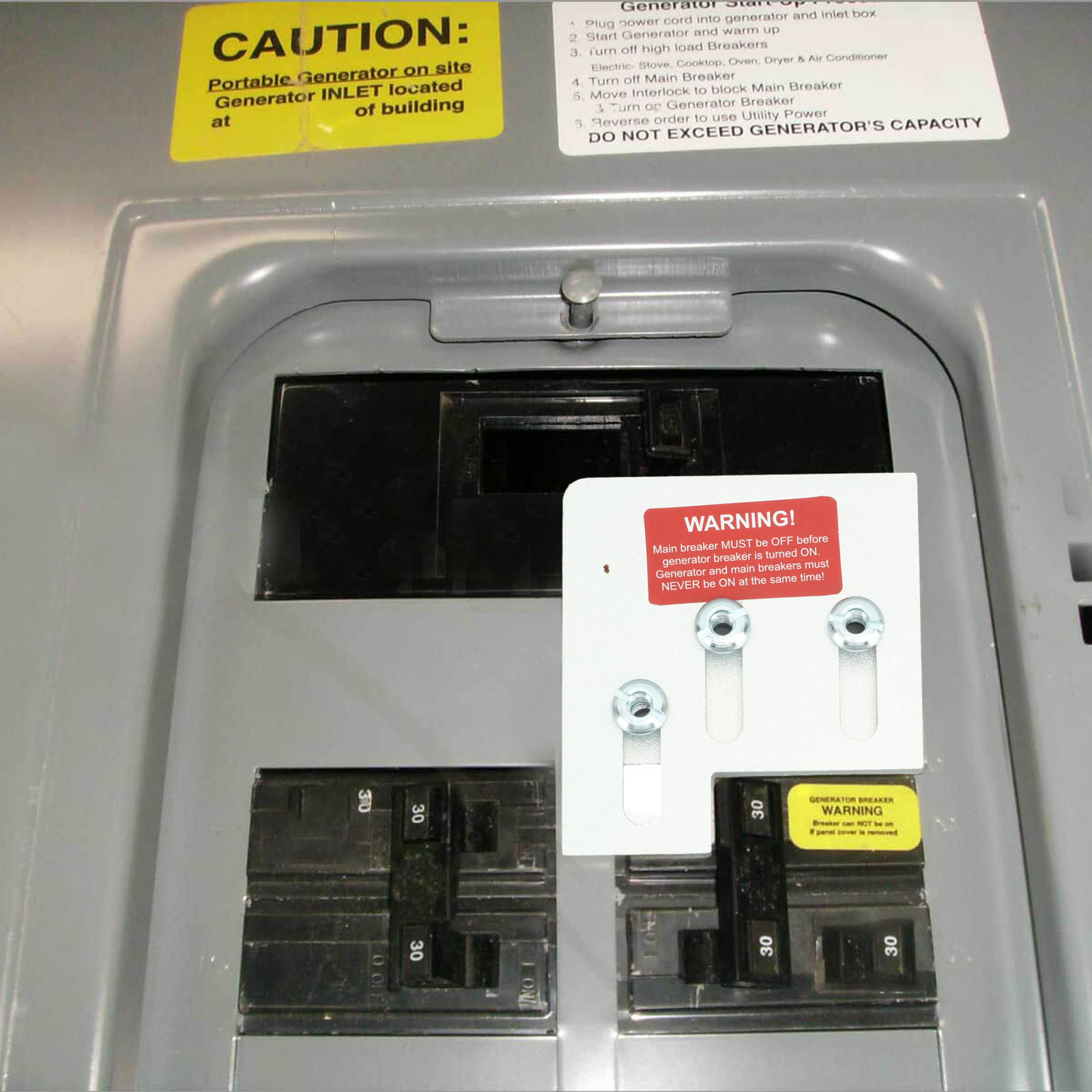
Small Square D QO panel. Two 2-pole breakers interlocked. |
Larger QO Panel. |
This device interlocks the main breaker with a subsidiary breaker. |
| Battery Inverter Systems | |
| Battery inverters create another source of AC power. Their prime function is to take DC power stored in a battery and convert it to AC to power loads (lights and appliances) in a home or business. | |
Most battery inverters are configured to also accept power from an external AC source in order to provide backup power in case the battery charge becomes low. This external power source is typically a generator, a utility feed or both. |
|
When the battery charge gets low the inverter will connect power from an external source to its output in order to maintain reliable power supply. That external source could be a utility feed or a generator. Some inverters are equipped to start a generator when external power is needed and stop the generator when it is no longer needed. The inverter does this power switching by utilizing a relay that is configured like the transfer switches above: There are wipers that can physically connect to either the inverter output or the external AC source but never allow the two sources to be connected together. The operation of this relay is automatic and provides reliable power to the loads. |
|
| If the inverter happens to experience an operational failure, the function of the internal transfer switch may be impaired. It may not transfer power from the external source even if it is present. In other words, if your inverter dies, it may not send generator power to your home even if the generator is running. | |
| For these circumstances, inverter manufacturers have provided a means to "bypass" the inverter and allow a manual transfer of power around the damaged inverter. This bypassing is accomplished with interlocked circuit breakers mounted in outboard cabinets that are part of what is known as Balance of System (BOS) components. | |
| Inverter Manufacturer-Provided Bypassing | |
| BOS cabinets were provided by manufacturers during the 2000s and 2010s. The most prevalent manufacturers of these systems were Outback Power and Xantrex (later acquired by Schneider). These systems relied on circuit breakers that were fitted with a moving "gate" assembly that would allow the circuit breaker from the inverter output to be turned on or the circuit breaker from the external power source to be turned on, but never both at the same time. This gate is another form of interlock. Below are photographs of some of these systems as provide by several manufacturers: | |
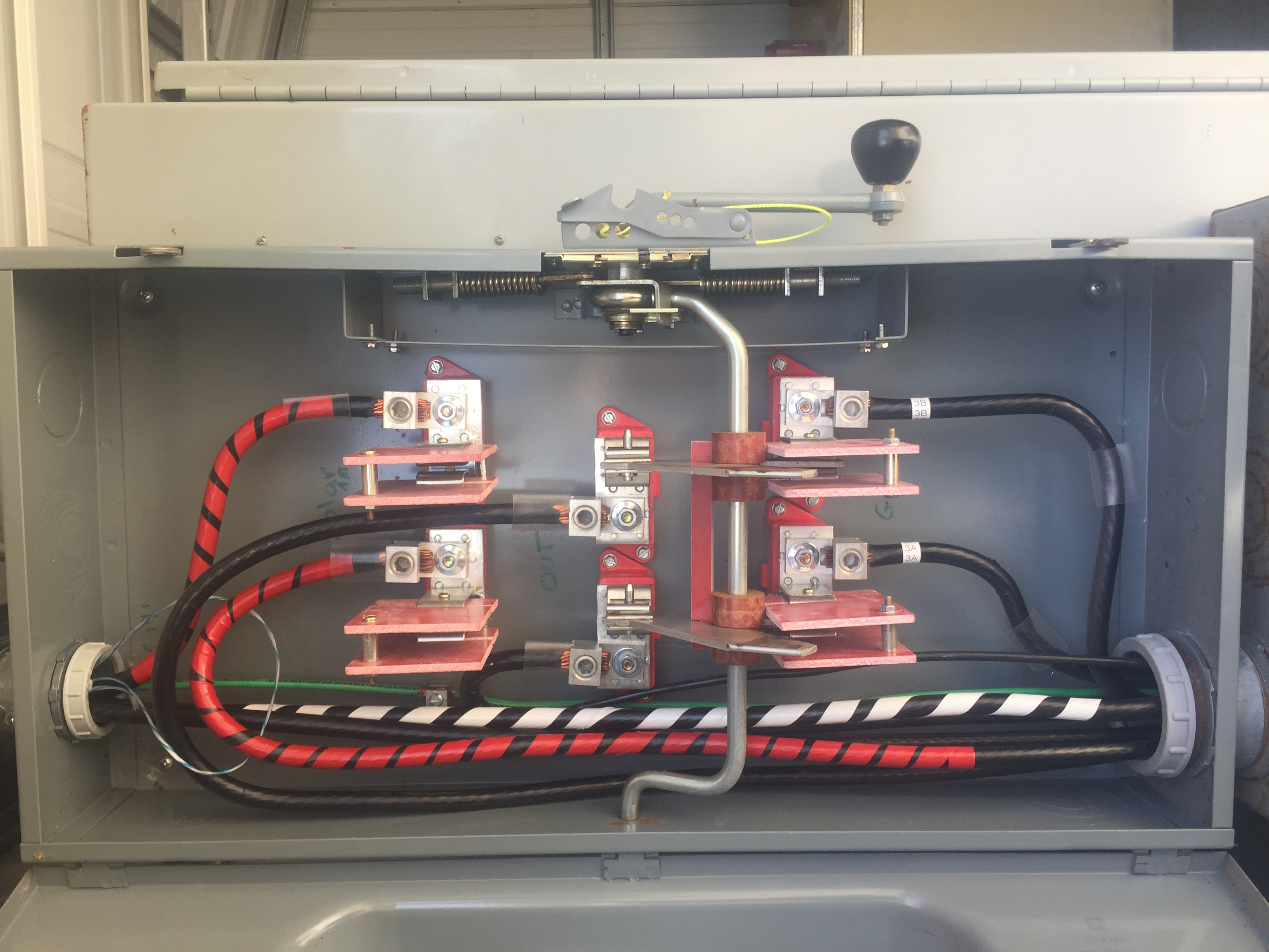
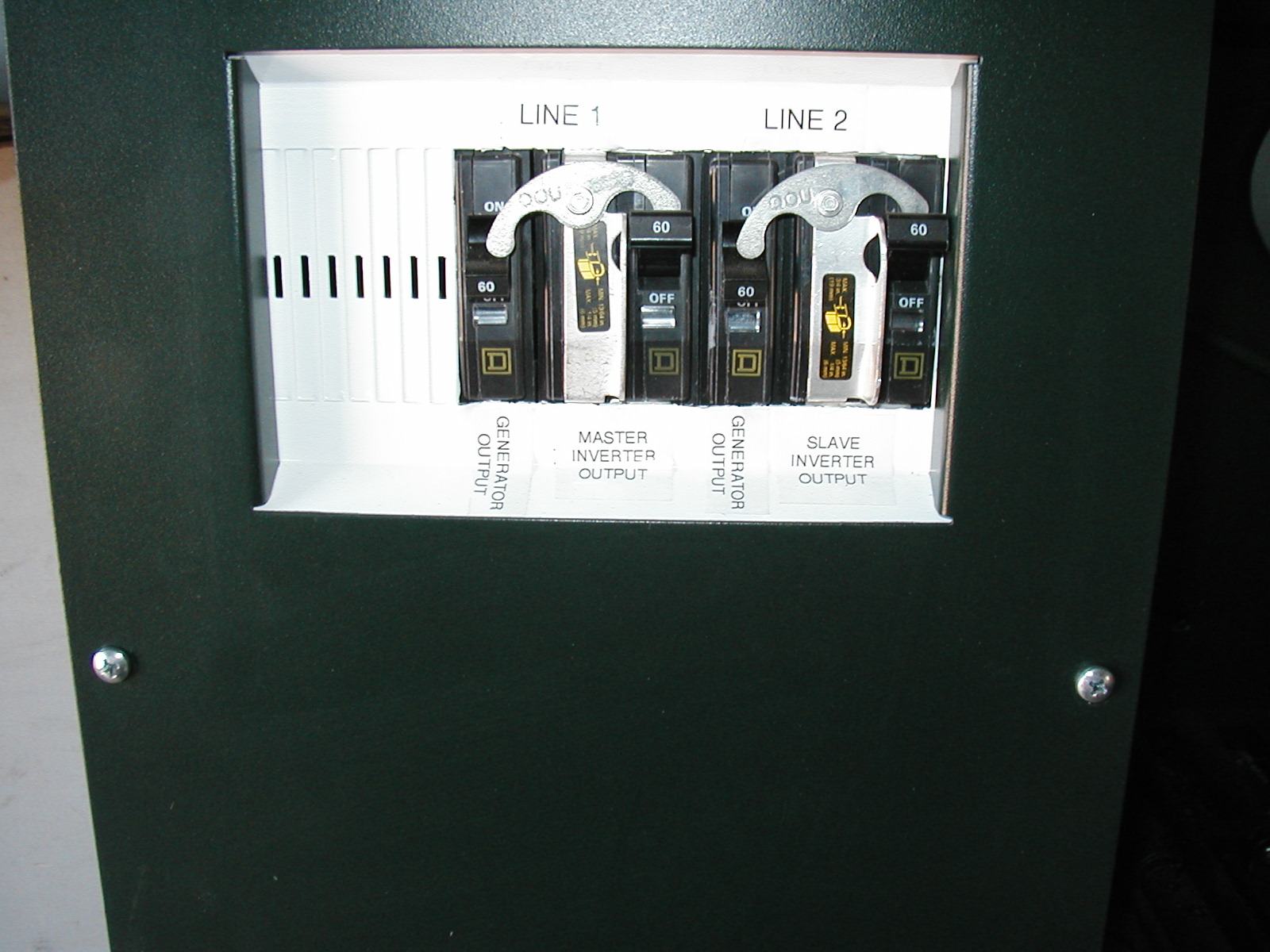
Outback provided a curved, swivelling interlock that allowed one or the other source to be connected to the output. I call these Rams Horns. |
Outback Rams Horns again. Earlier versions, shown above, bypassed each hot phase individually. This was awkward in that one phase could be transferred and the other not, a scenario not recommended. |
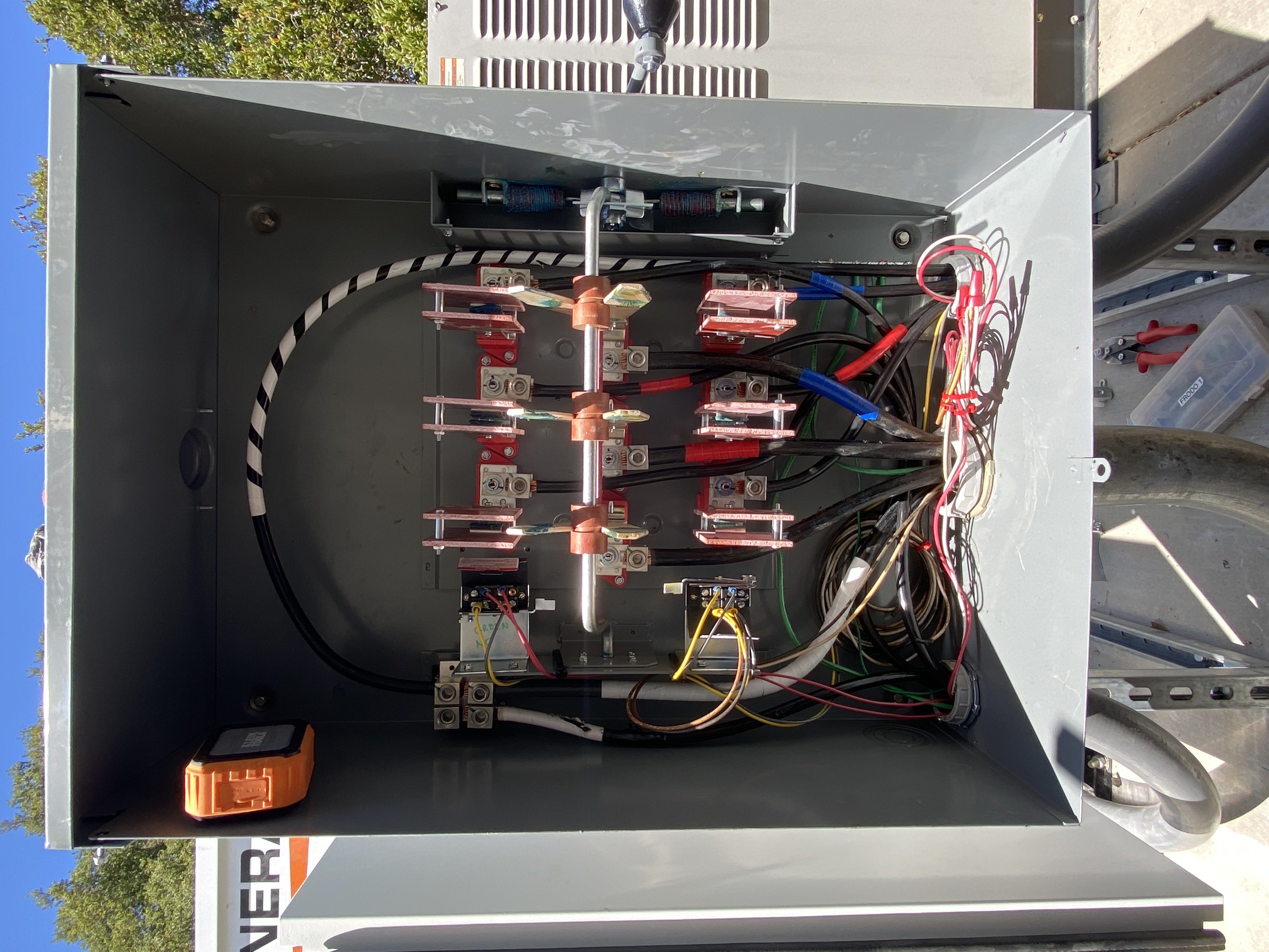
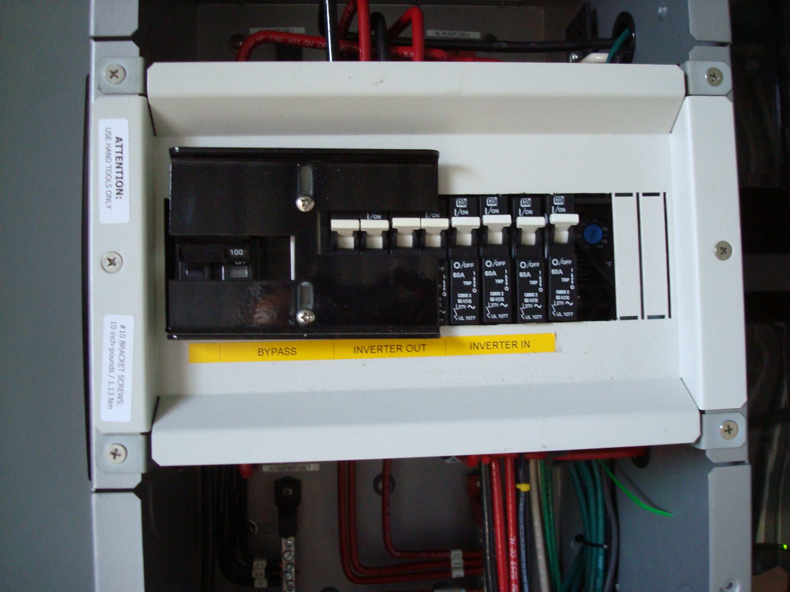
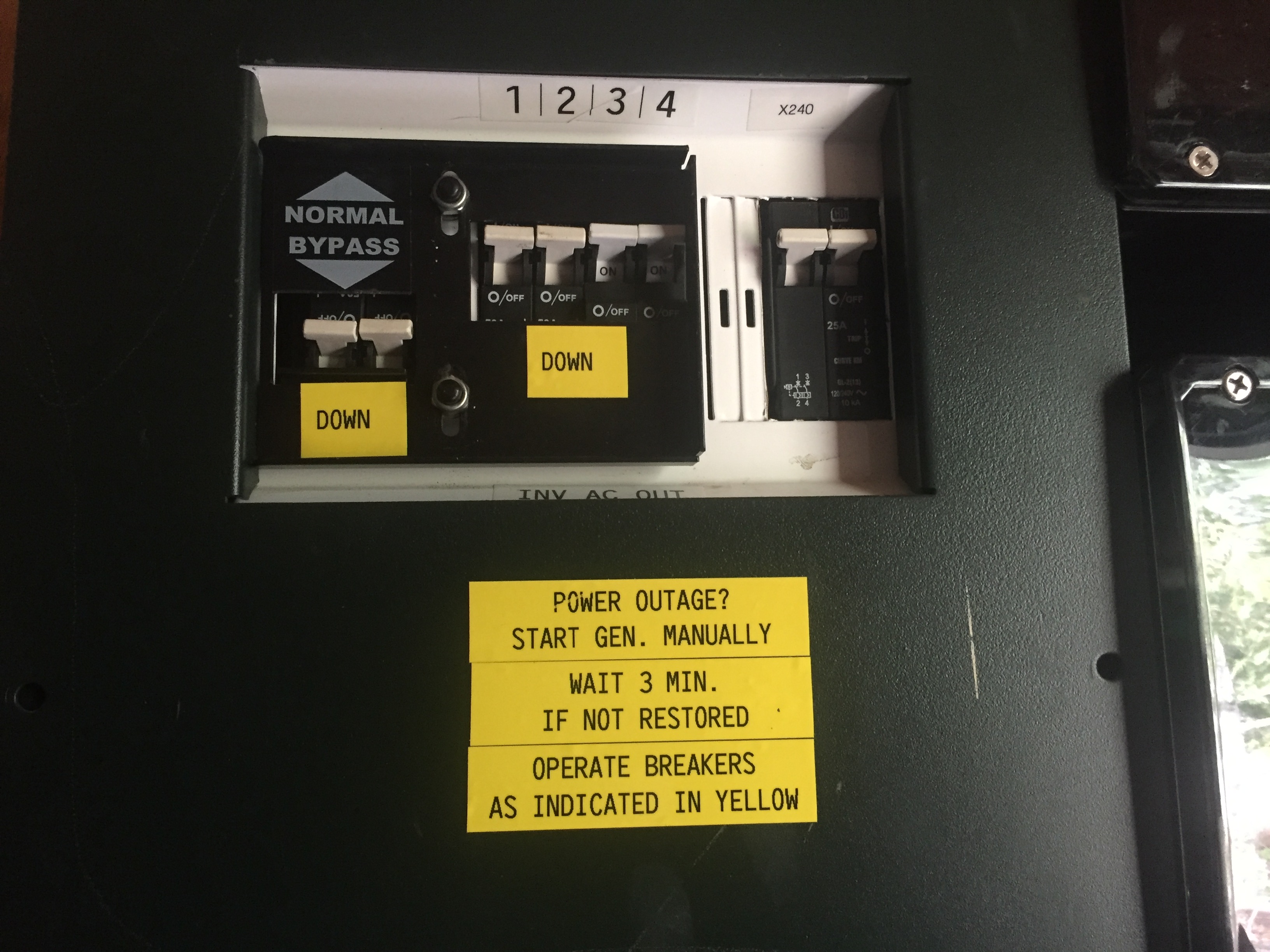
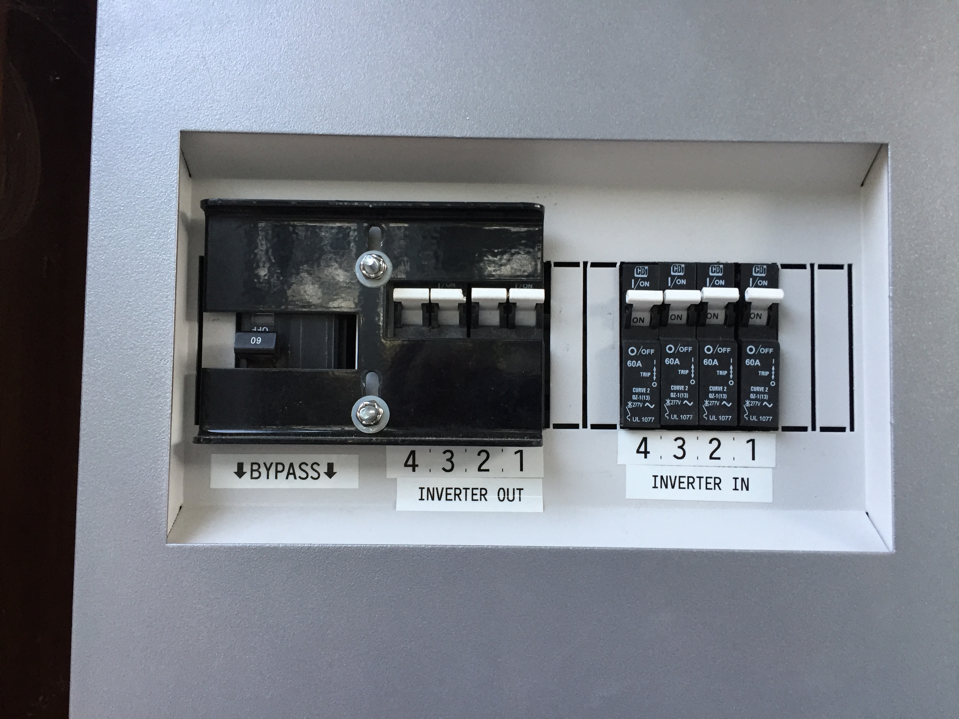
Later on slide plates became popular. These allowed one set of circuit breakers to be turned on only if the other set were turned off. This was accomplished by installing one set of breakers upside down. It allowed one, two or four inverters to be bypassed in favor of a generator or utility supply. |
Instructions provided on or near the bypass plate. |
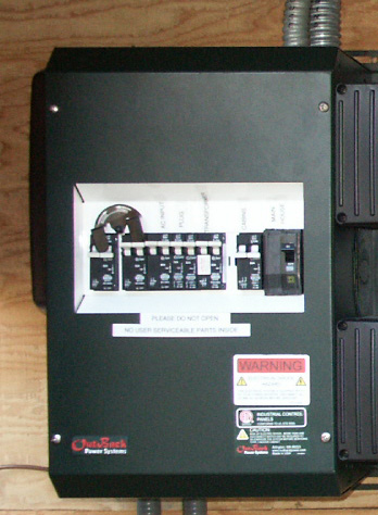
Flexware 250 system. |
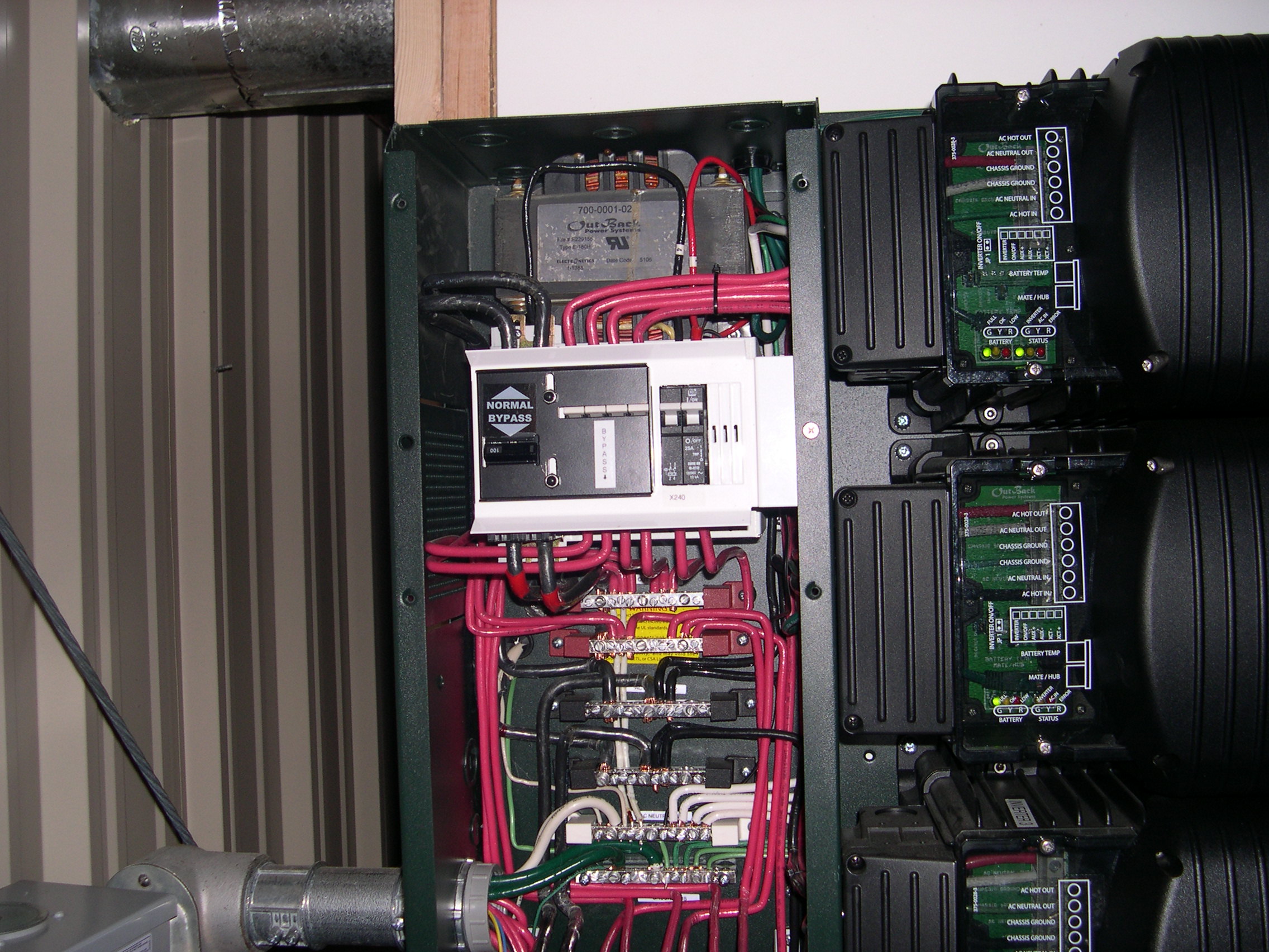
An Outback Flexware system. |
Here you can see the internal wring. |
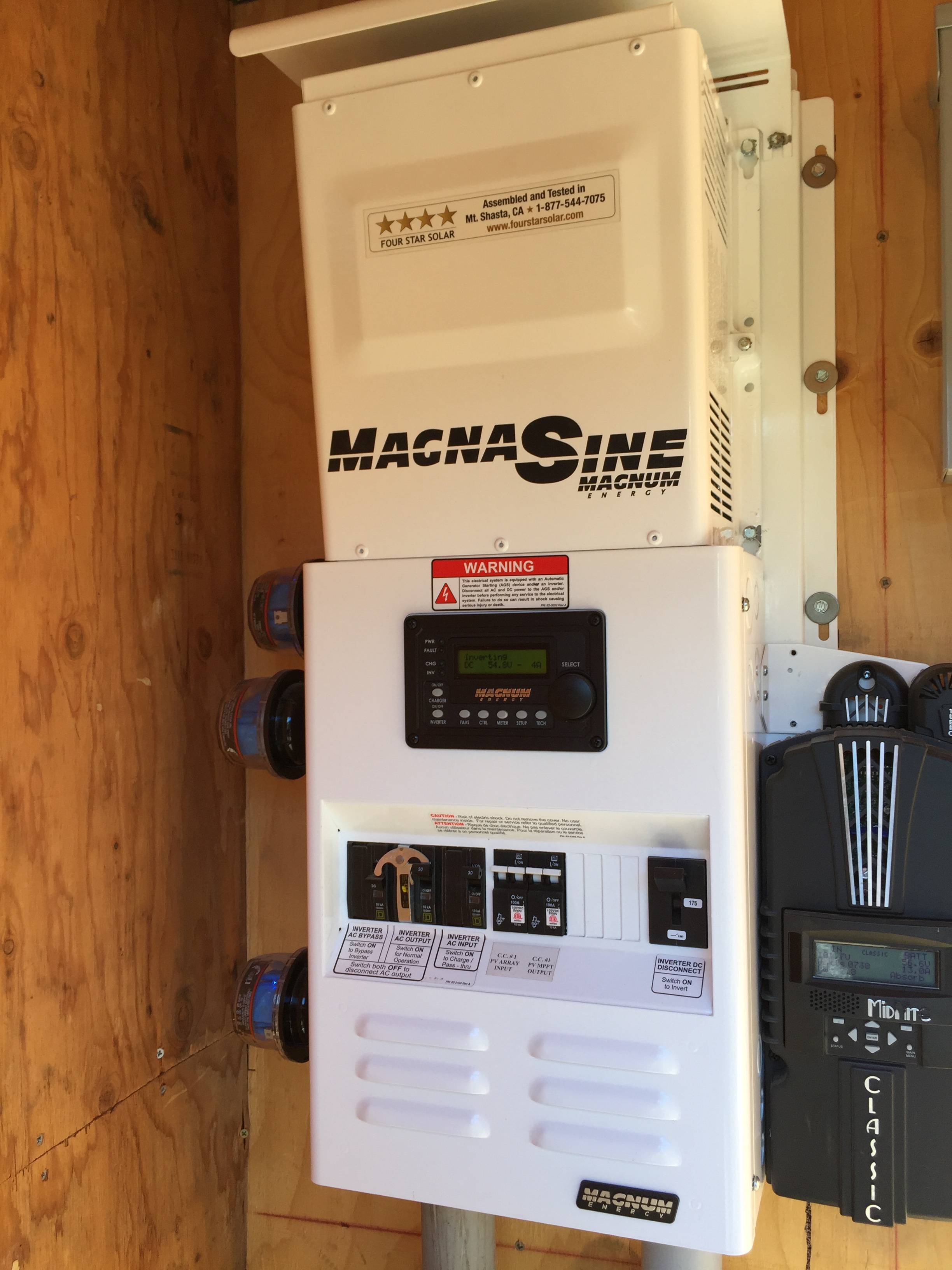
A Magnasine with bypass. |
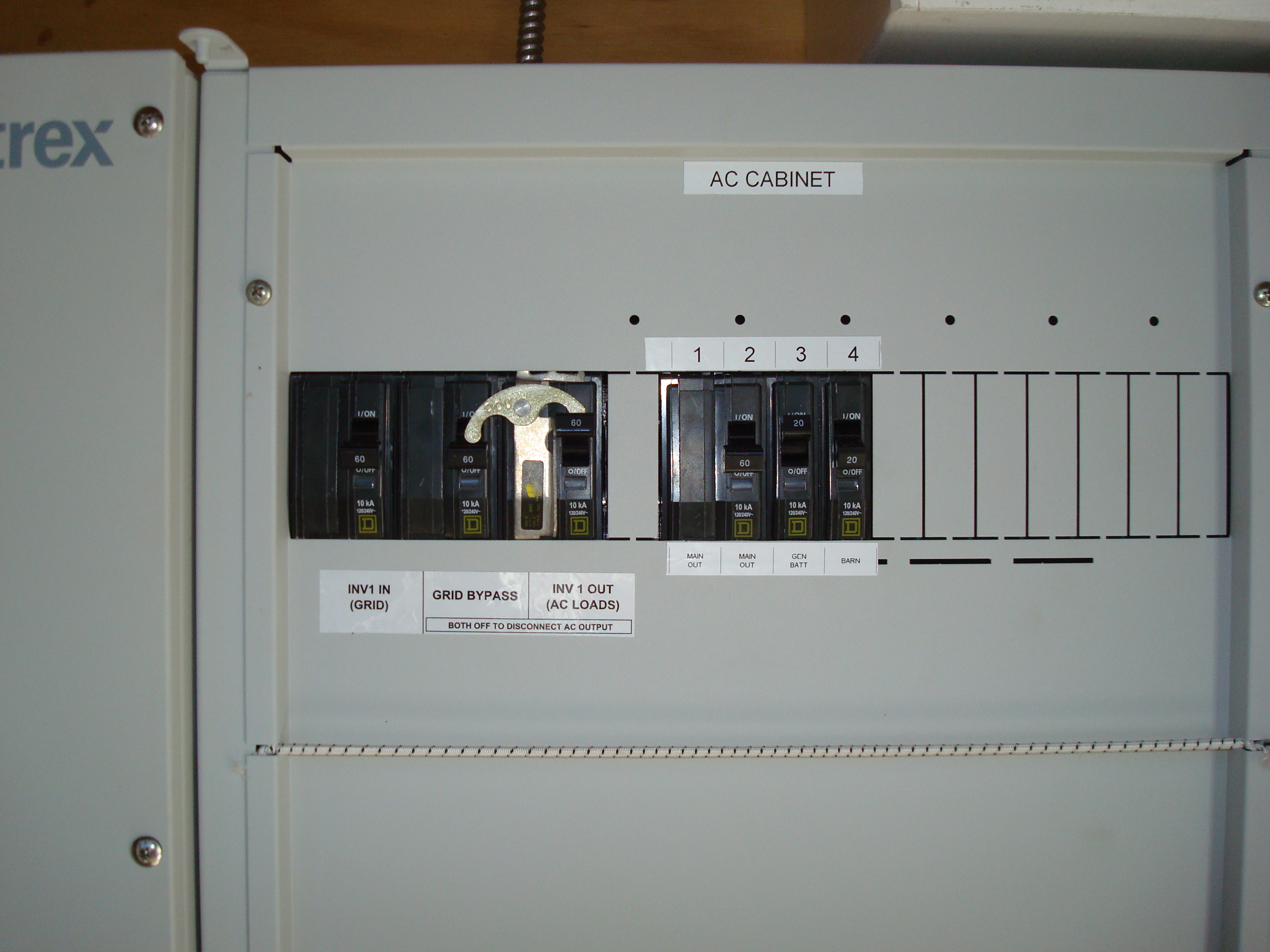
This is a Xantrex XW system we installed with a simple bypass interlock. |
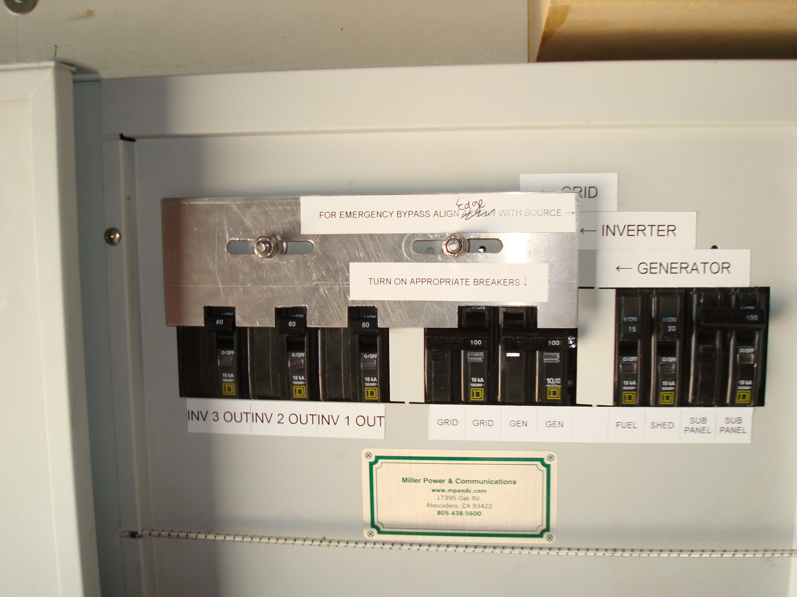
This XW system was more complicated: It had 3 inverters, a generator feed and a utility feed. The slide-plate will allow combining and sending three inverters to the loads, or the utility or the generator. |
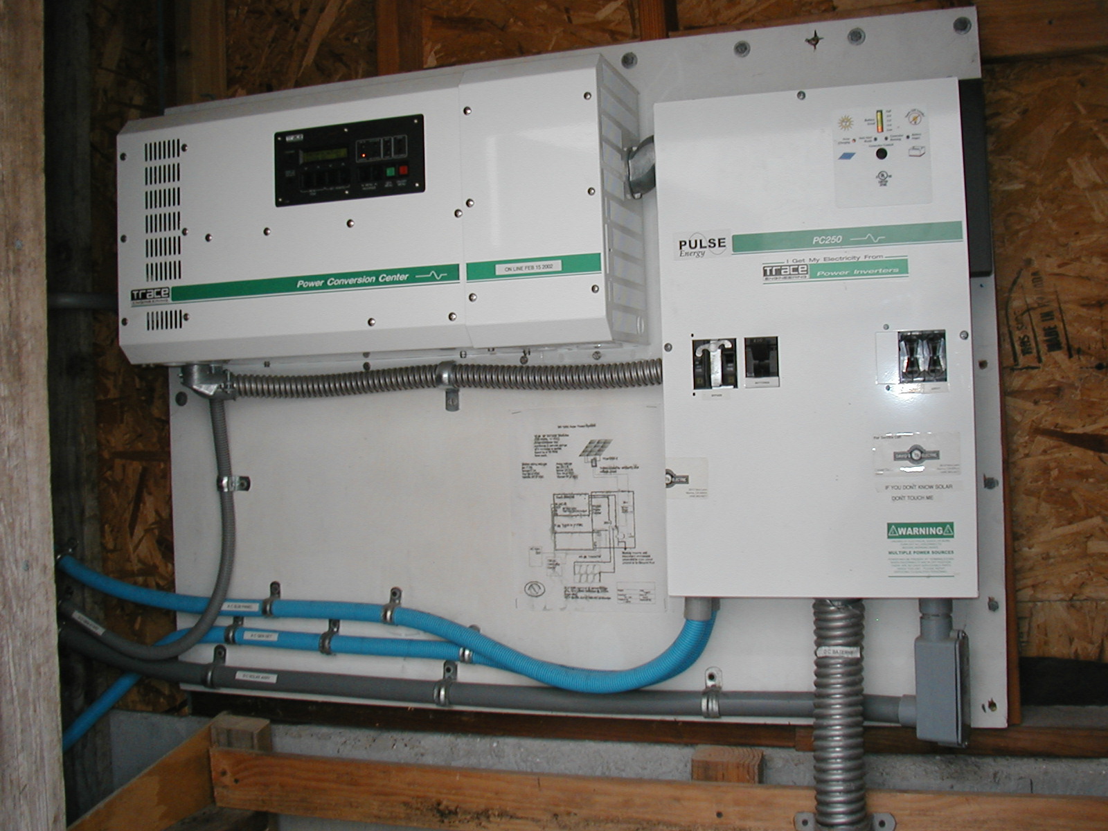
This is a rare Xantrex/Pulse power system with bypass capabilities. |
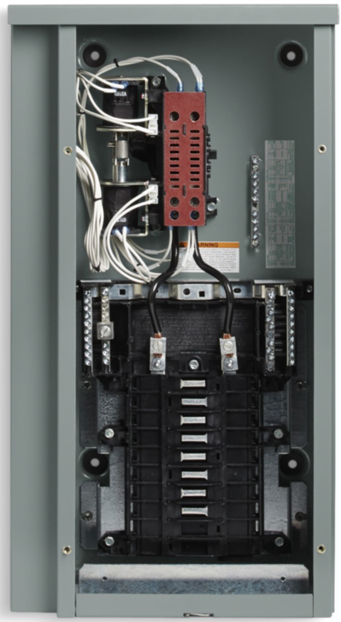
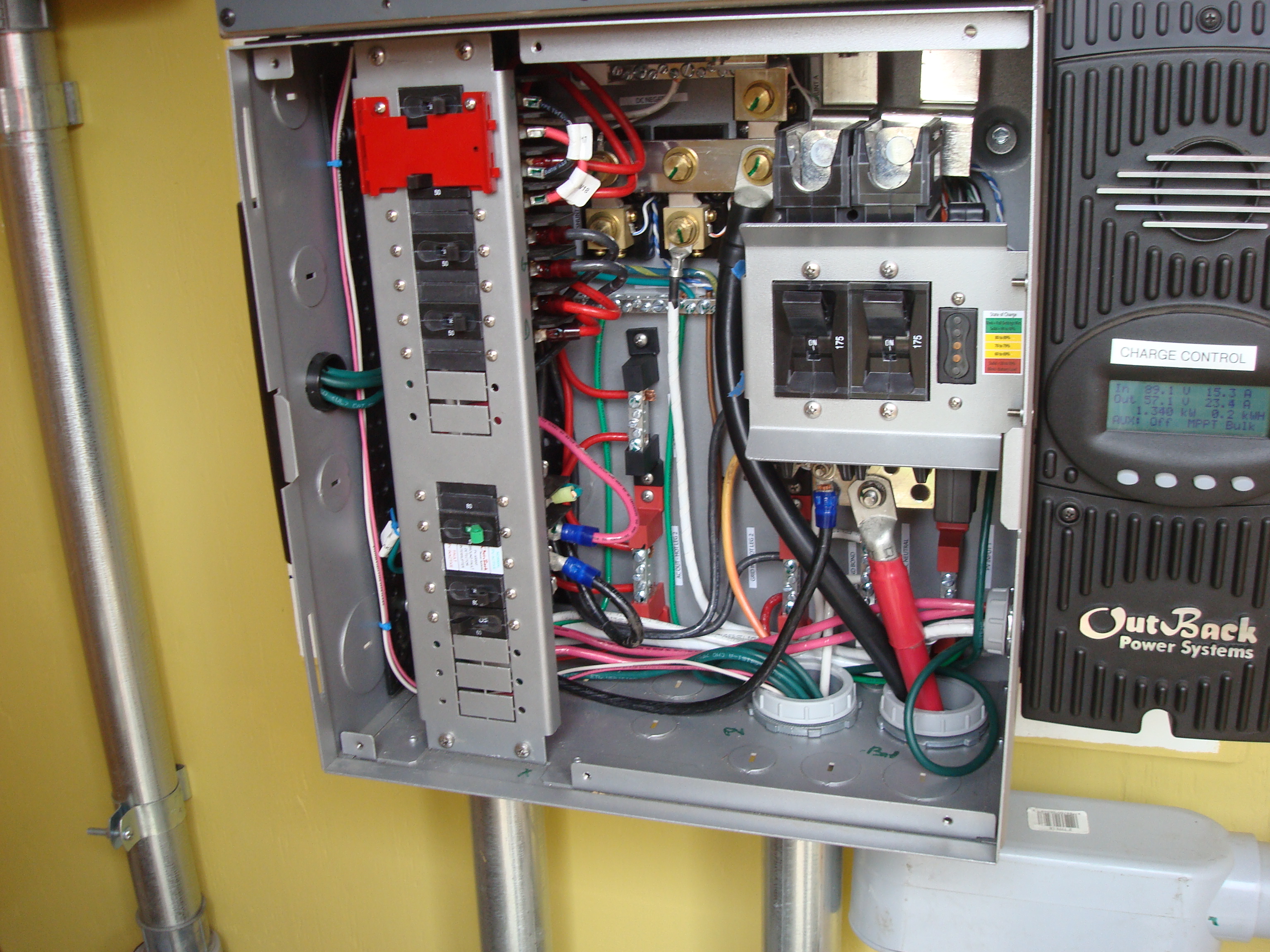
The BOS cabinet for the more recent Outback Radian series was called the GSLC. The red plate is the interlock. It was an unfortunate design in that the circuit breakers were wired with connections to studs at the back of the circuit breakers. These were very tedious to install and service. This system was my motivation to remove all AC circuit breakers from the GSLC and locate them in OTS breaker panels. Bypassing required interlocks usable in OTS cabinets. |
| Limitations of BOS Bypassing | |
| There are two limitations to manufacturer-provided BOS bypassing schemes: | |
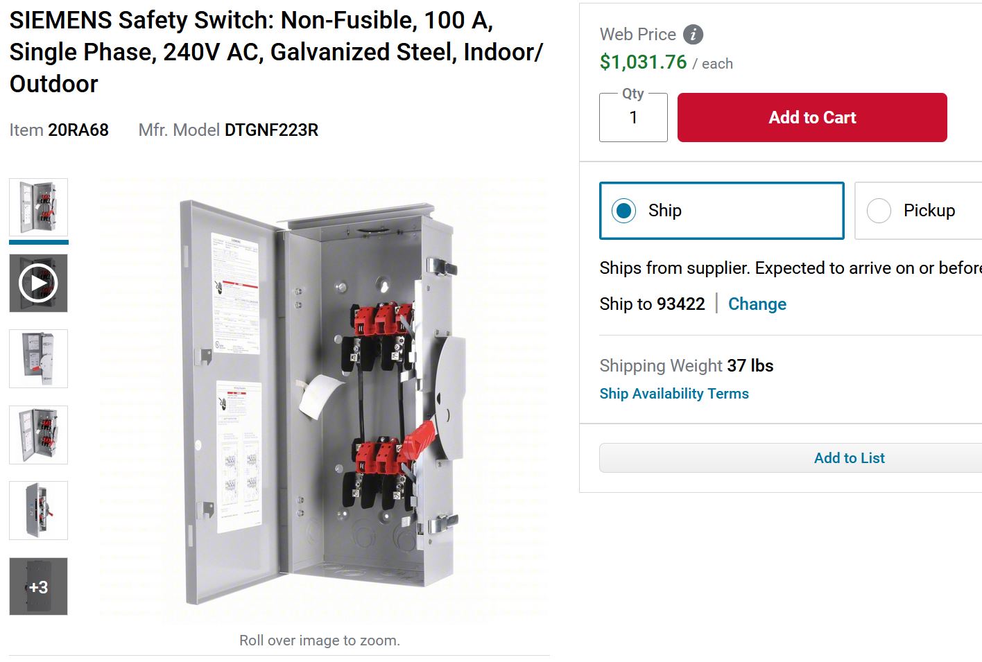
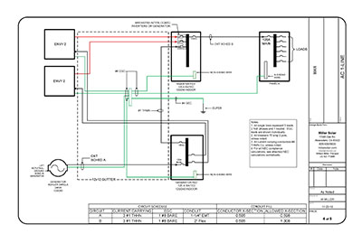
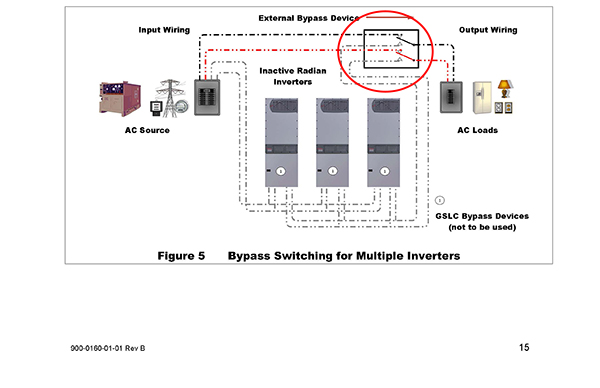
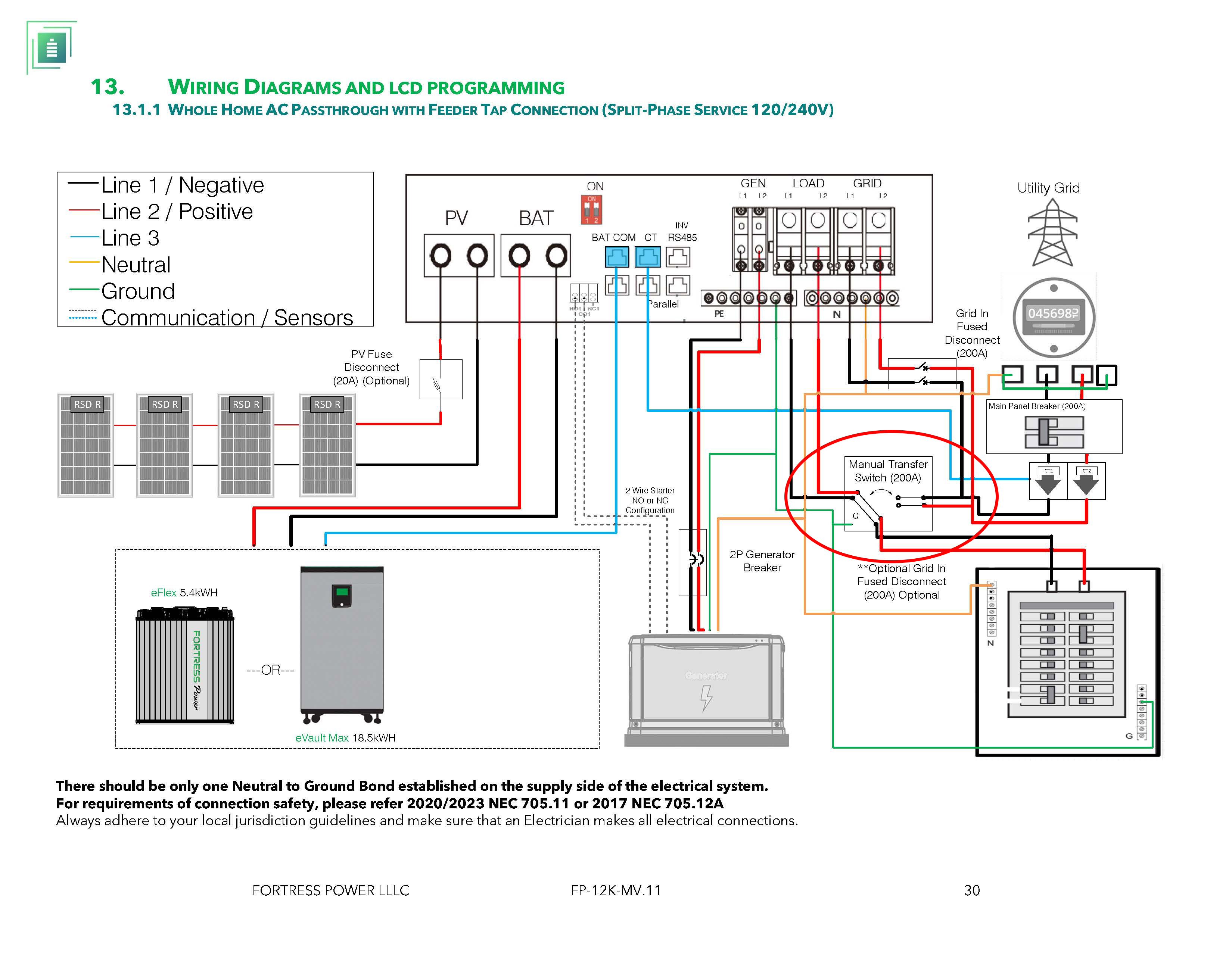
| 1. These inverters are designed for multiples of these units to be used in parallel if more capacity is needed. If the BOS bypassing cannot accommodate multiple inverters you are suggested to use an expensive outboard manual transfer switch, like the manual transfer switches we discussed above. Below is a wiring diagram from an inverter manufacturer suggesting this: |
|
 |
|
These transfer switches can be expensive. |
|
| 2. Newer inverters are not offered with any BOS cabinets. They have input and output circuit breakers within the inverter cabinet but there is no bypassing feature offered. These inverters are suggested to be installed with the expensive manual transfer switches. See below. |
|
 |
|
| Innovations | |
| Instead of purchasing expensive and bulky manual transfer switches it is possible to provide bypass capabilities using interlocks fitted to Off-the-Shelf breaker panels. | |
If you have no more than one inverter to bypass, the interlocks provided by a breaker panel manufacturer might be adequate, although they are not all well designed and some operate awkwardly. If, however, you have more than two inverters to bypass, none of the factory manufactured interlocks will work. |
|
To fill this gap, I developed a multi-inverter bypass interlock. This device is in the form of a sliding plate that, in one position will allow multiple inverters to feed an output, and in the other position, will allow an external power source, such as a generator to power the loads. Below are some photos of various interlocks I have designed and built: |
|
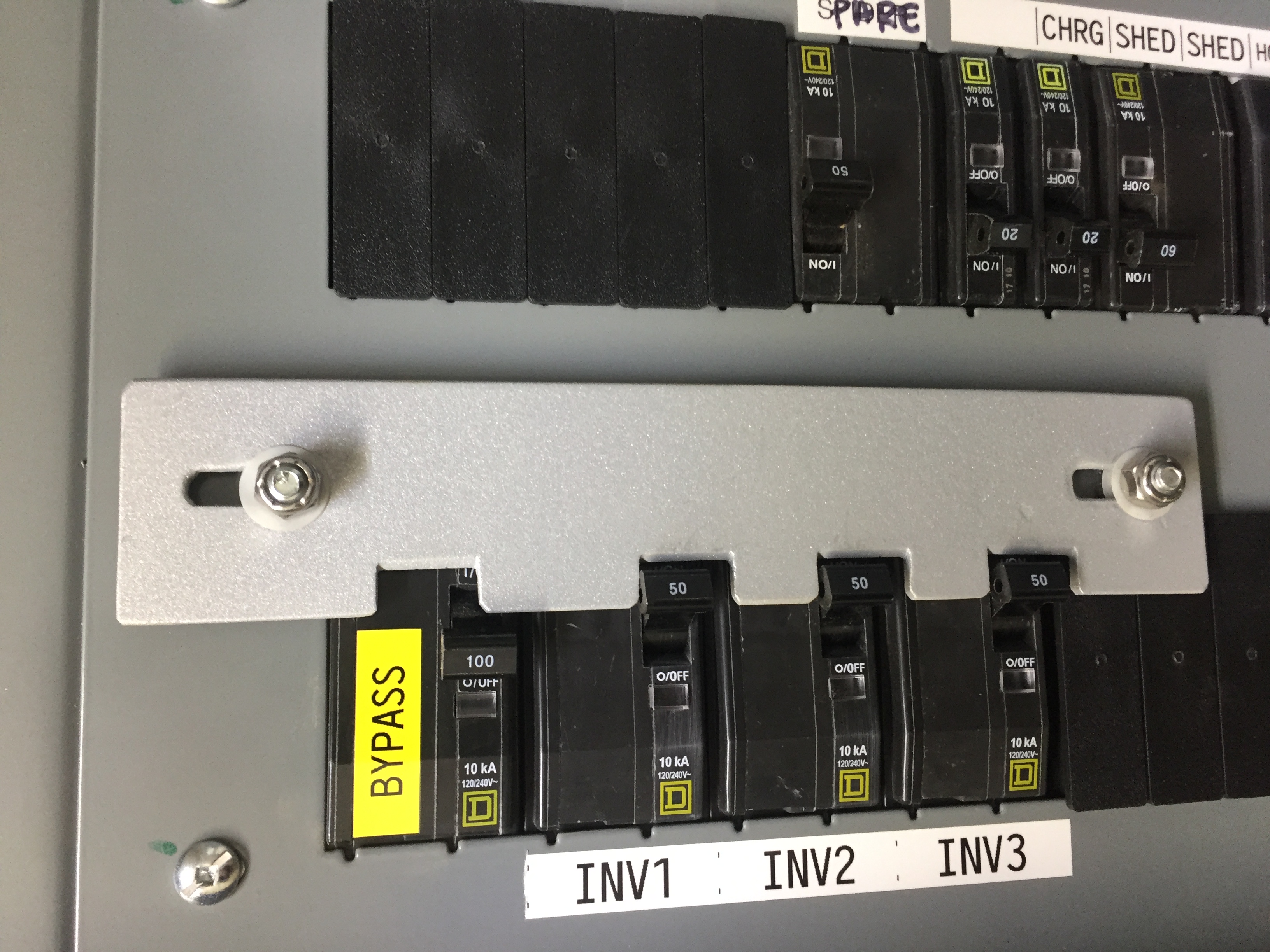
Three inverters interlocked. |
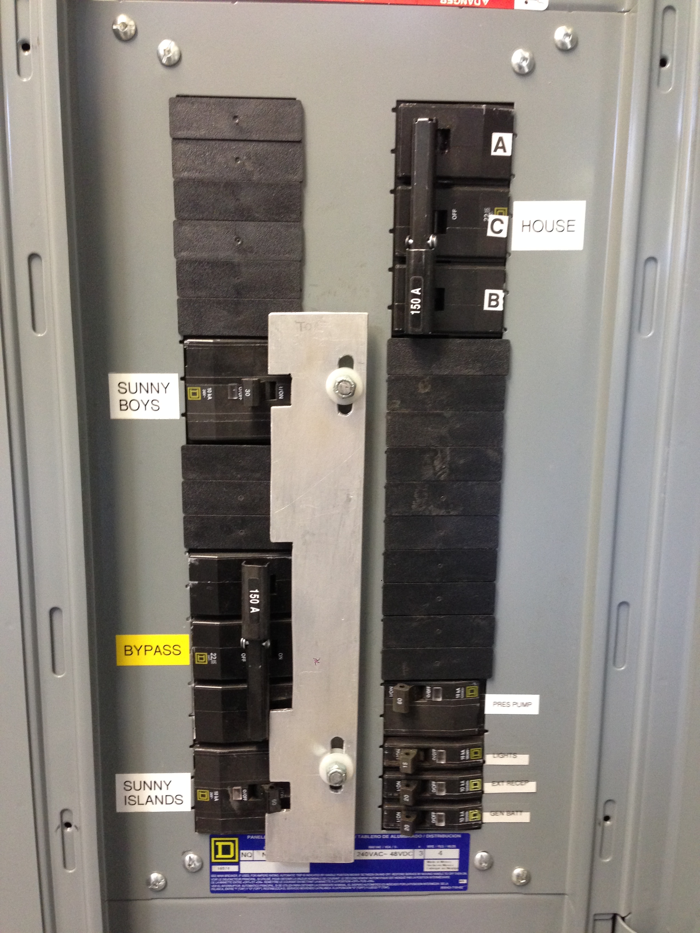
The bypass is interlocked with the outputs of 3 Sunny Boys combined in a separate panel and 4 Sunny Islands combined in another separate panel. |
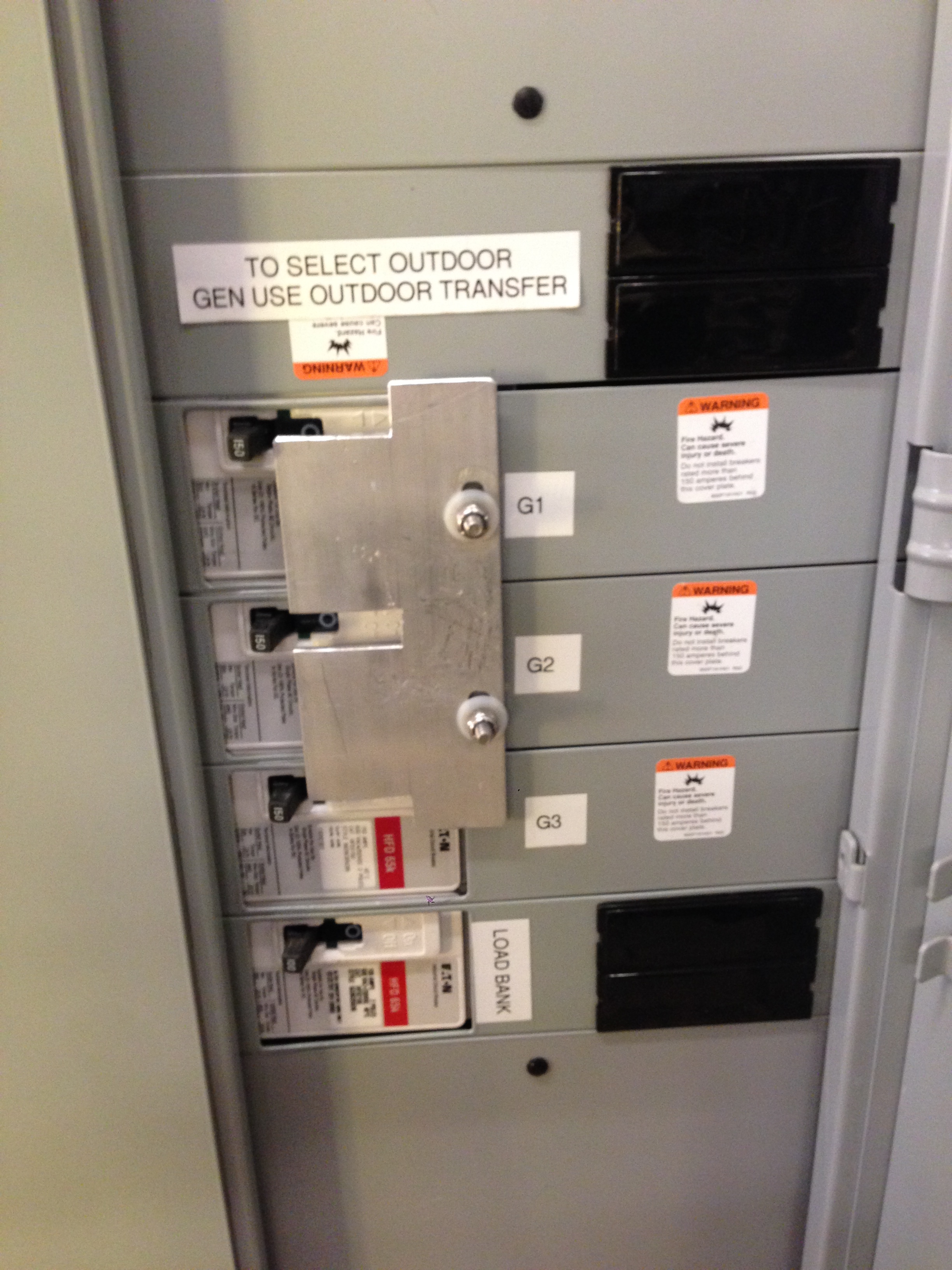
This one is a bit different: there are 3 backup generators in this facility and this interlock allows the selection of only one generator at a time. |
This interlock slides to one side or the other,allowing only one breaker to be turned on at a time. |
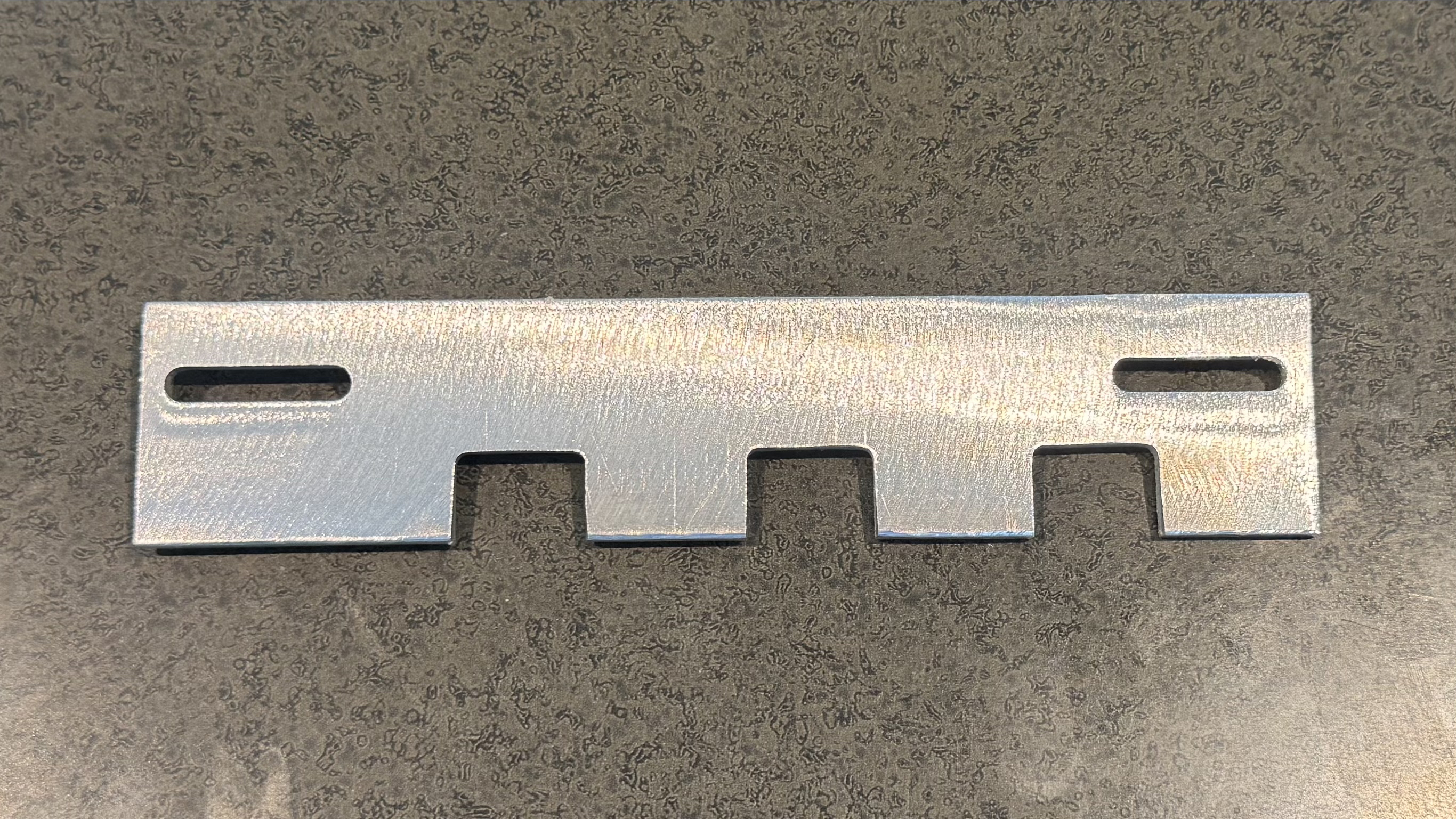
The universal interlock: After many years of custom fabricating interlocks unique to each installation I decided to try and design an interlock that will work for just about any battery inverter installation. The parameters were: 1. Allow for bypassing 1 to 4 inverters. 2. Fit SquareD QO panels (20 space or larger). Below is the device that fits these criteria and a brief summary of how it was designed and fabricated. |
|
 |
|
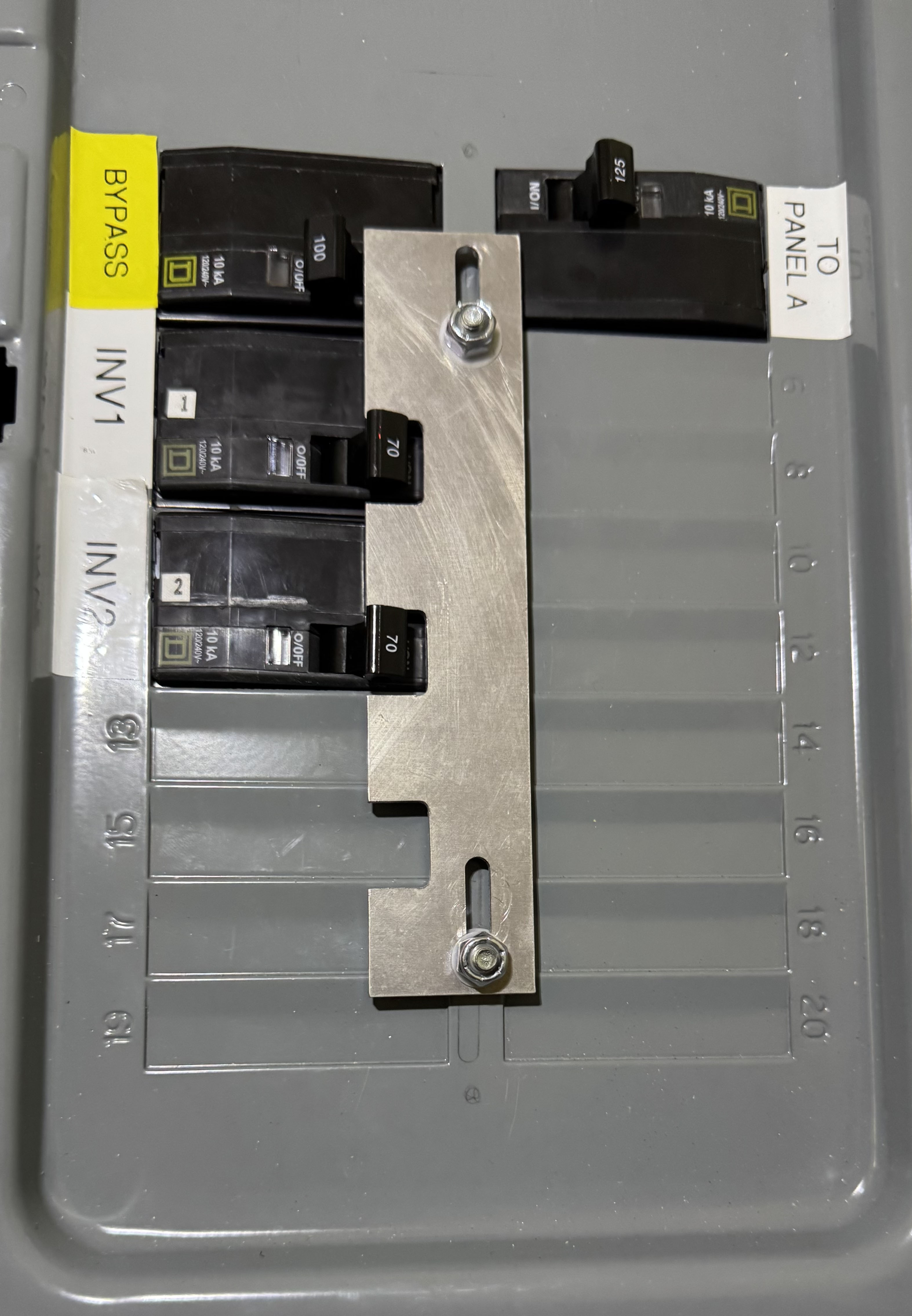
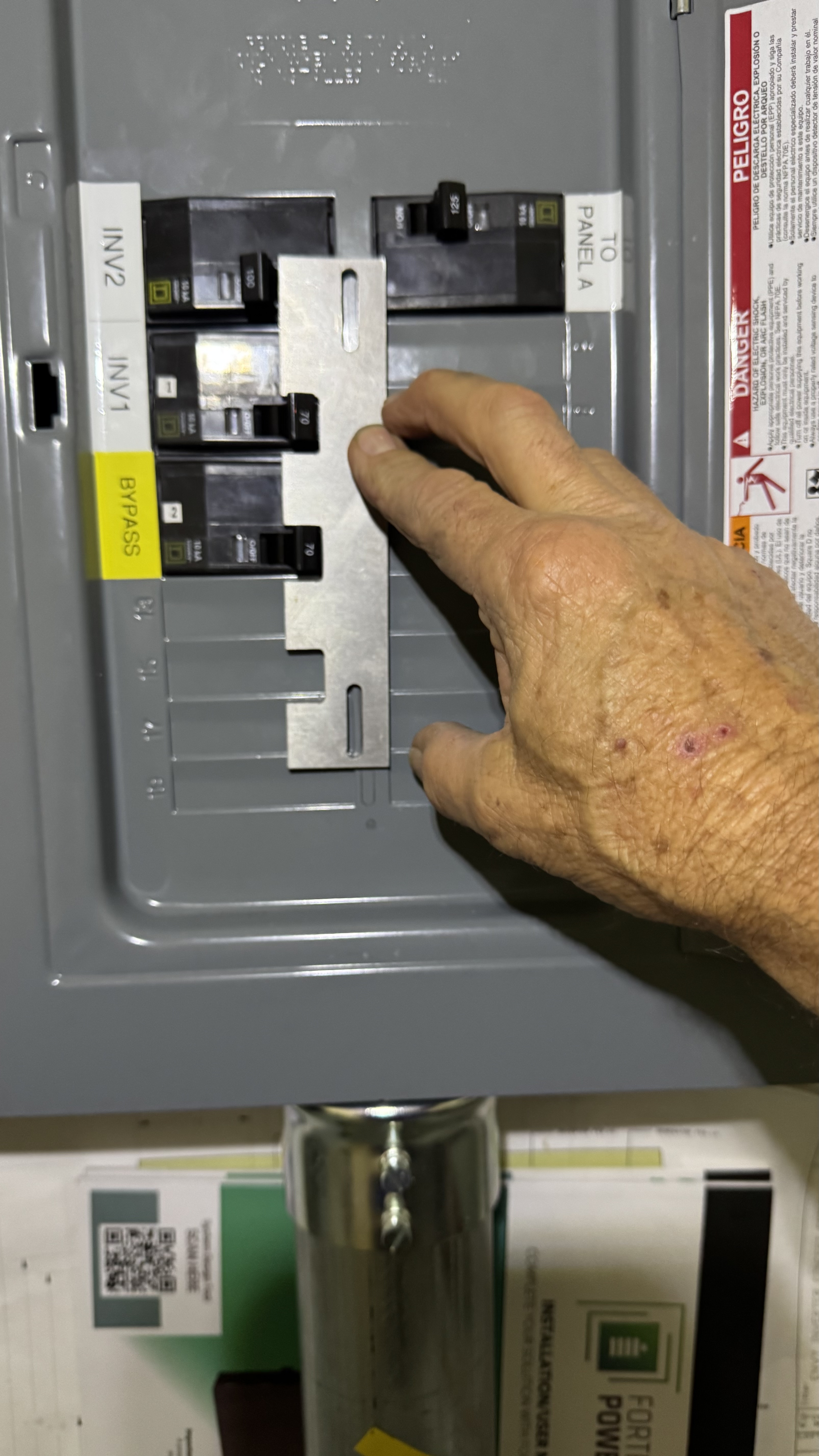
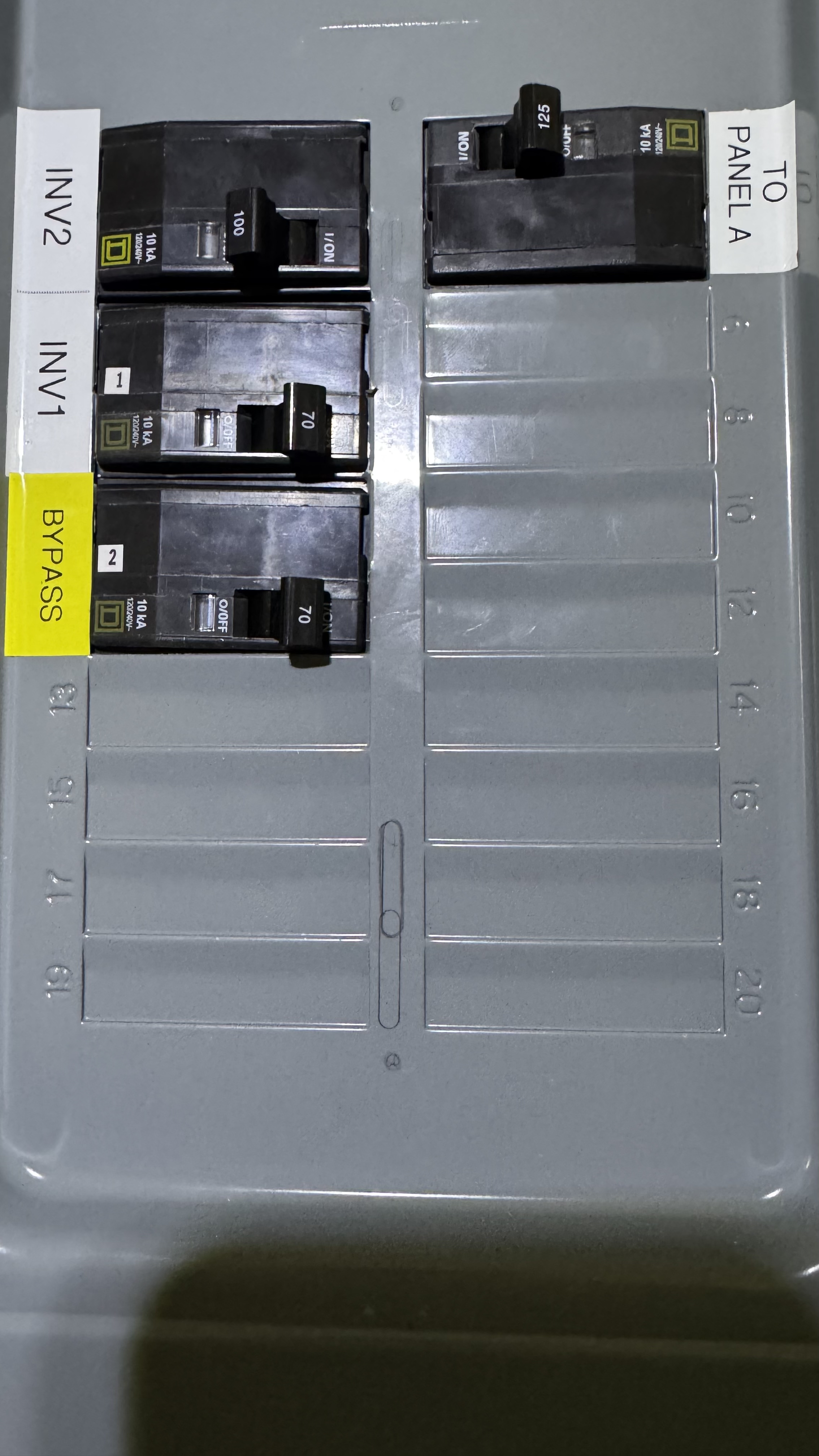
Normal operation with 2 inverters: The generator bypass is off and the inverter outputs are on. |
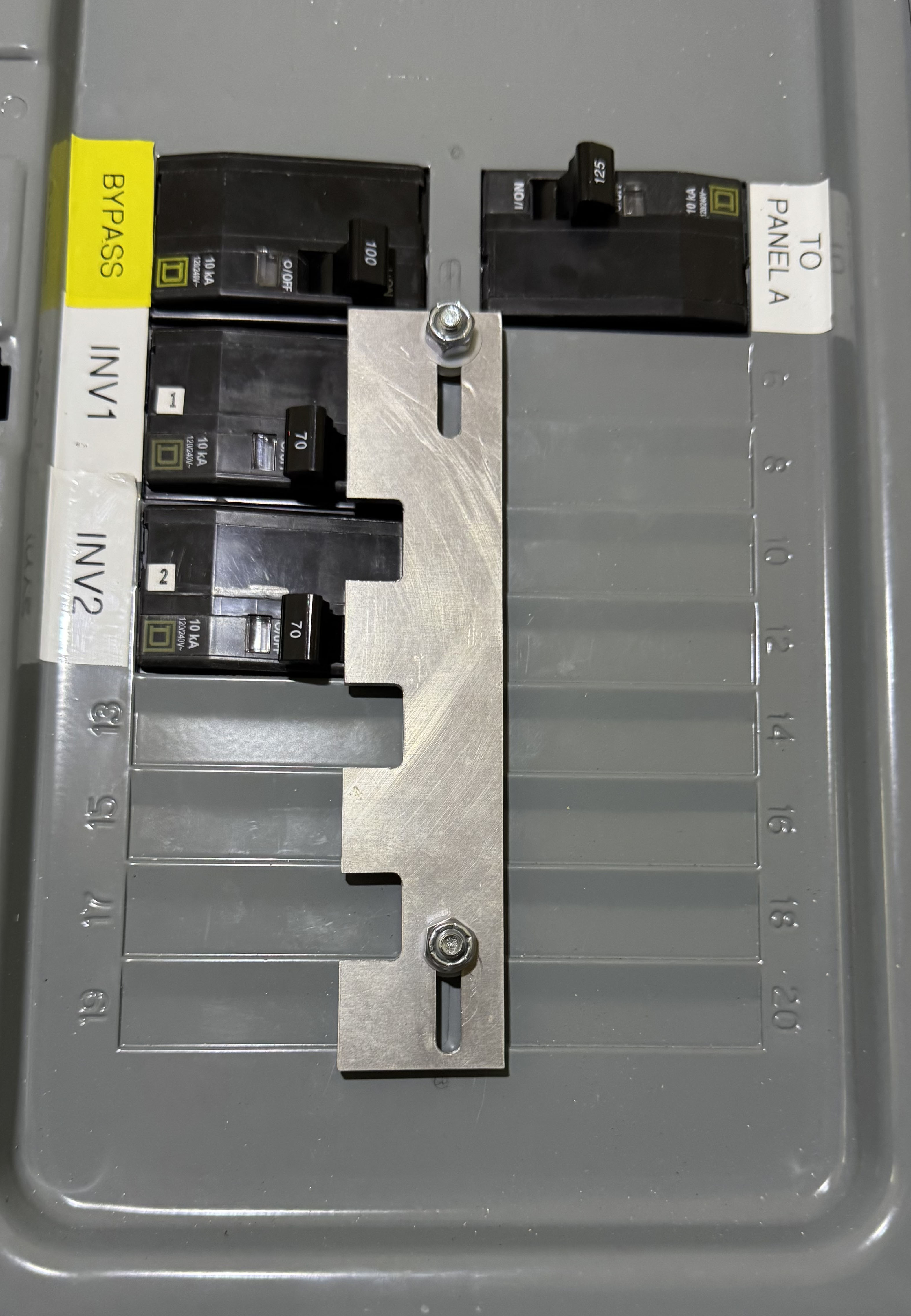
Bypassed operation: The inverter outputs are off and the generator bypass is on. |
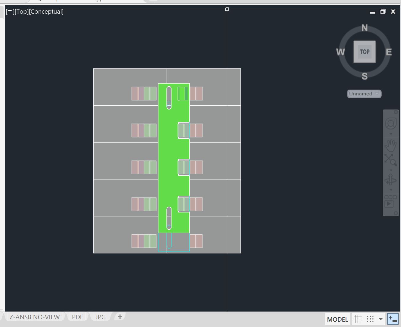
This is the CAD file for the project. Tthe interlock can change for right or left installation simply by fliping it over. |
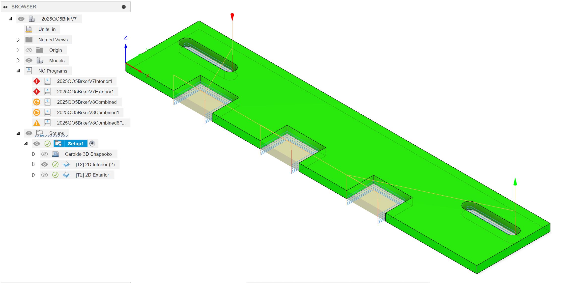
The 3D model is imported into Fusion 360 to develop the tool paths. |
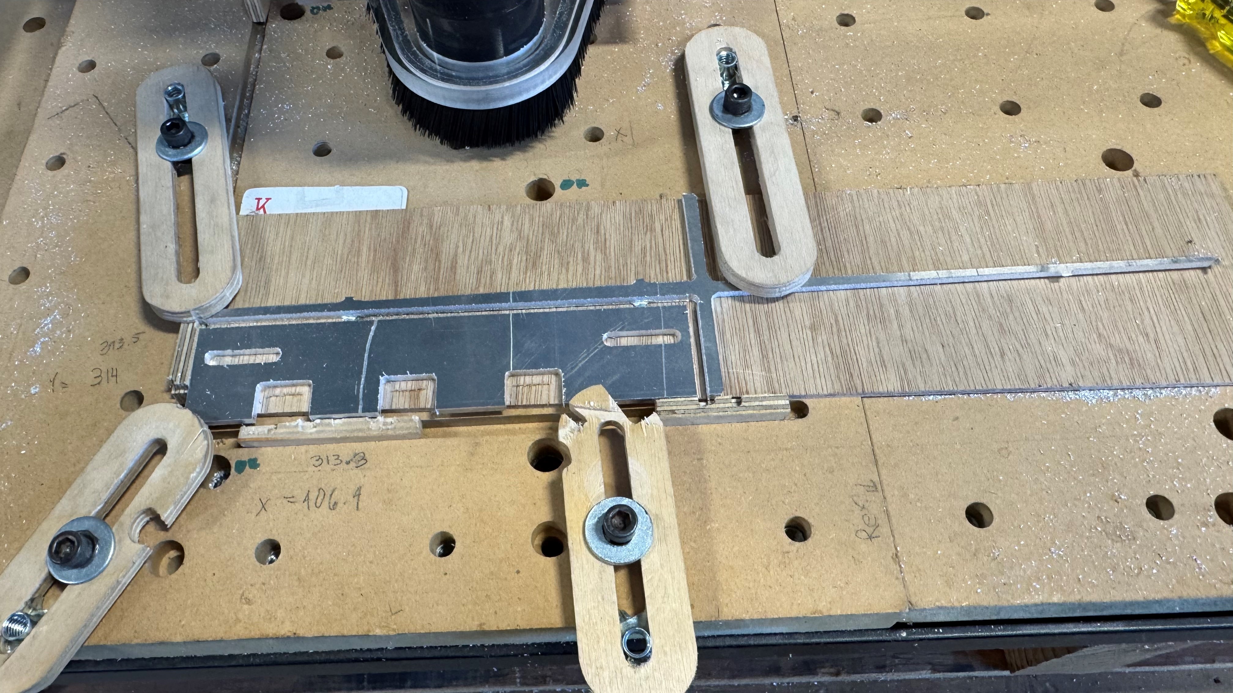
The interlock is cut out on a CNC router. |
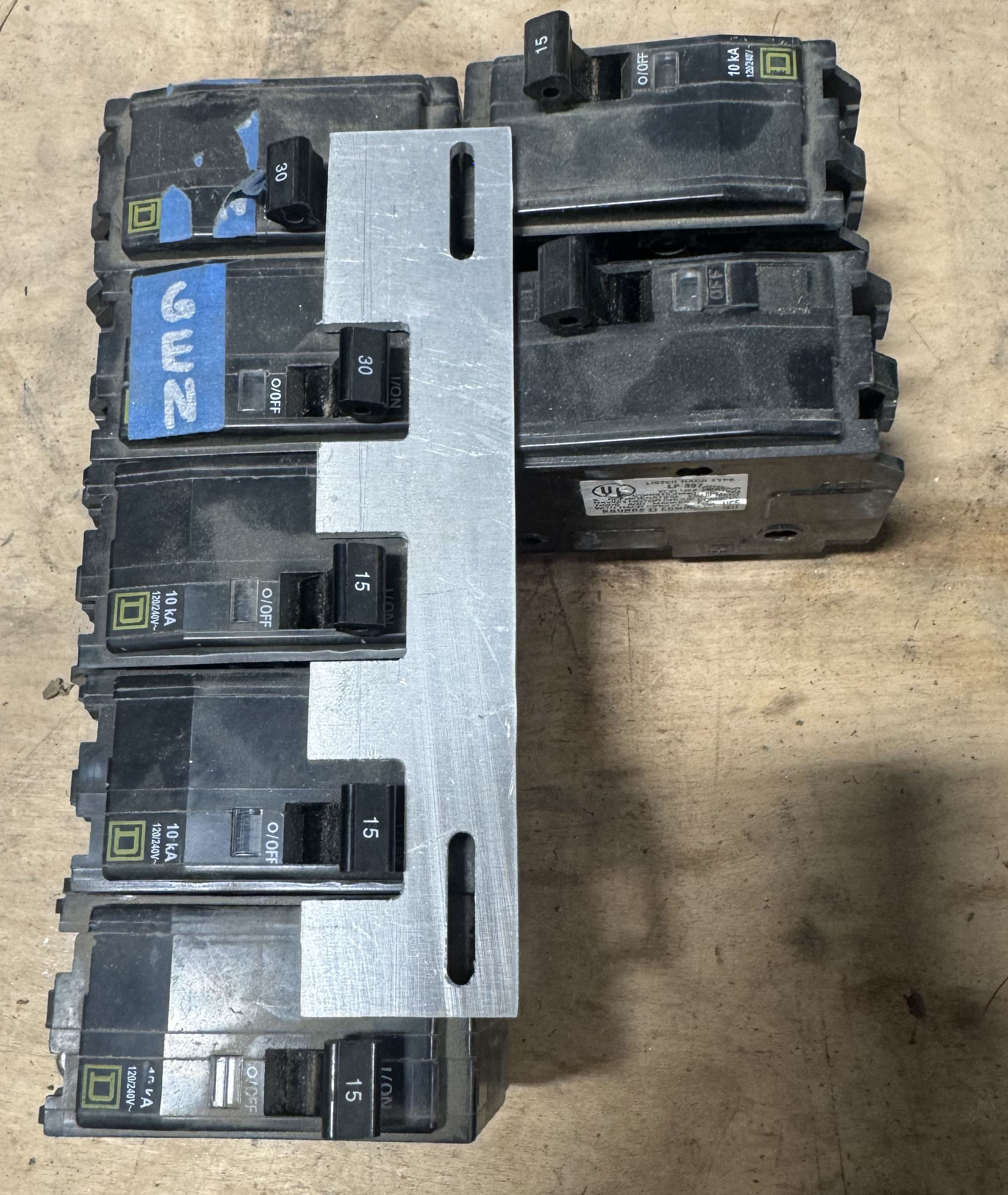
I test the fit with breakers on the bench. |
I am finding the location for the studs. I hold the interlock in one position and trace the slots... |
Then I hold the interlock in the other position and trace the slots again. |
Where the slots overlap is where the studs are located. The studs are 10-32 X 3/4" flat head screws. Onto these studs are stacked a nut, nylon washer, interlock, nylon washer and a nylock nut. The nylock is adjusted for smooth movement of the interlock. |
Here is the final product. There is space to add 2 more 2-pole inverter breakers. The interlock does not interfere with any breakers on the right side. |
|
|
Summary: Providing a means to bypass a battery inverter is a necessity in case of inverter failure. If the system has only one inverter an interlock provided by the manufacturer of a breaker panel will be sufficient. You can always acquire a mechanical transfer switch but these are expensive and take up a lot of room. A good option is a custom fabricated breaker interlock. |
|
| In the near future I hope to make these interlocks available for purchase. Contact me if you are interested. | |